Wheel machining clamp

A wheel machine and fixture technology, which is applied in the direction of manufacturing tools, metal processing equipment, metal processing machinery parts, etc., can solve the problems of deviation, uneven wall thickness, etc., and achieve easy operation, uneven wall thickness and simple structure Effect

Pending Publication Date: 2022-01-25
CITIC DICASTAL
View PDF0 Cites 0 Cited by
  • Summary
  • Abstract
  • Description
  • Claims
  • Application Information

AI Technical Summary

Problems solved by technology

[0003] The purpose of the present invention is to provide a wheel machining fixture, which can realize the high-precision positioning and clamping of the new type of wheel machining with vertical stripe groove structure on the inner rim, and solve the problems of uneven wall thickness and deviation

Method used


Image

  • Wheel machining clamp
  • Wheel machining clamp
  • Wheel machining clamp

Examples


Embodiment Construction

[0018] It should be noted that, in the case of no conflict, the embodiments of the present invention and the features in the embodiments can be combined with each other.

[0019] The technical solutions of the present invention will be clearly and completely described below with reference to the accompanying drawings and in conjunction with the embodiments. Apparently, the described embodiments are only some, not all, embodiments of the present invention. Based on the embodiments of the present invention, all other embodiments obtained by persons of ordinary skill in the art without making creative efforts belong to the protection scope of the present invention.

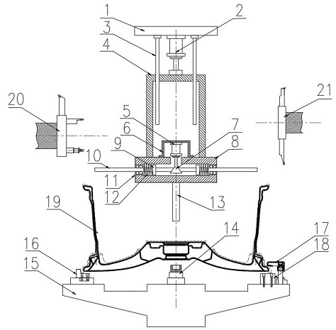
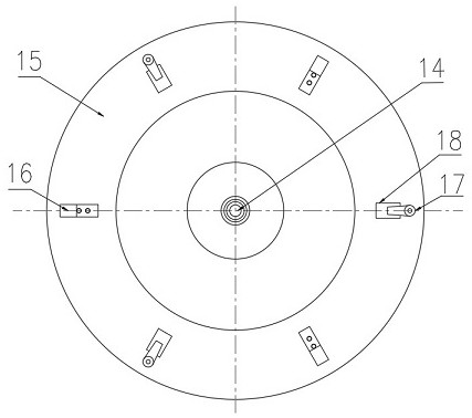
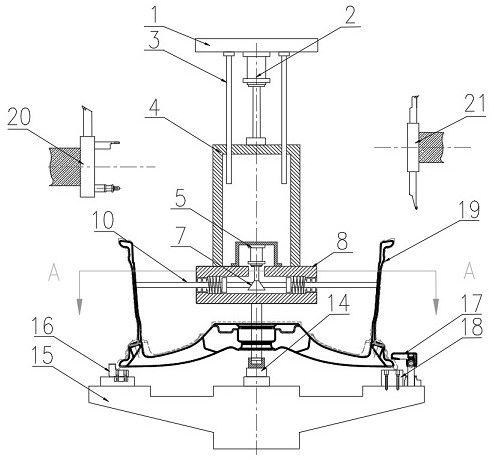
[0020] Refer to the attached Figure 1-4 The wheel machining fixture according to the embodiment of the present invention will be described in conjunction with the embodiments.

[0021] A wheel machining fixture, consisting of a base 1, a cylinder 2, a guide column 3, a sleeve 4, a positioning cylinder 5, a mounting...


PUM


Abstract

The invention relates to a wheel machining clamp. The wheel machining clamp comprises a base and a chuck, wherein the base is fixed to the top of a machine tool, the center of the chuck is provided with a center bottom base, a plurality of positioning blocks are evenly distributed on the chuck in the circumferential direction and used for wheel positioning, an air cylinder is installed in the center of the base, guiding columns are evenly installed around the air cylinder, the output end of the air cylinder is connected with a sleeve, and the other end of the sleeve is connected with a flange plate; a sliding way is arranged in the flange plate, a positioning air cylinder is installed on the flange plate through an installation frame, the output end of the positioning air cylinder is connected with a wedge-shaped block, positioning rods make contact with the wedge-shaped block and are arranged in the built-in sliding way, and a center column is installed in the center of the bottom of the flange plate and is coaxial with the center bottom base. The wedge-shaped block synchronously drives the three positioning rods to achieve high-precision positioning and clamping in machining of a novel wheel with an inner rim vertical stripe groove structure, and the problems of uneven wall thickness, vehicle deviation and the like are solved; compared with an existing clamp, the wheel machining clamp is simple in structure and more convenient to operate.

Description

technical field [0001] The invention relates to the technical field of wheel machining fixtures, in particular to a wheel machining fixture. Background technique [0002] With the development of wheel manufacturing technology, there are more and more lightweight and high-strength new wheel hubs. Both the inner wall and outer wall of the traditional wheel hub need to be turned. A new type of lightweight wheel only turns the outer rim, and the inner rim is no longer turned. Casting surface, in order to strengthen the strength, there are vertical stripe grooves on the casting surface, if this kind of wheel adopts the traditional wheel machine to add fixtures, it will cause problems such as uneven wall thickness of the rim, deviation and other problems, which will affect the performance of the wheel. This patent is based on this status quo , to provide a wheel machining fixture, which can realize the high-precision positioning and clamping of the wheel machining of this new stru...

Claims


Application Information

Patent Timeline
IPC IPC(8): B23Q3/00B23Q3/18
CPCB23Q3/00B23Q3/18B23Q2703/10B23Q2703/04
Inventor 刘会莹朱利利郭建东吴国瑞
Owner CITIC DICASTAL
Why Eureka
Try Eureka