

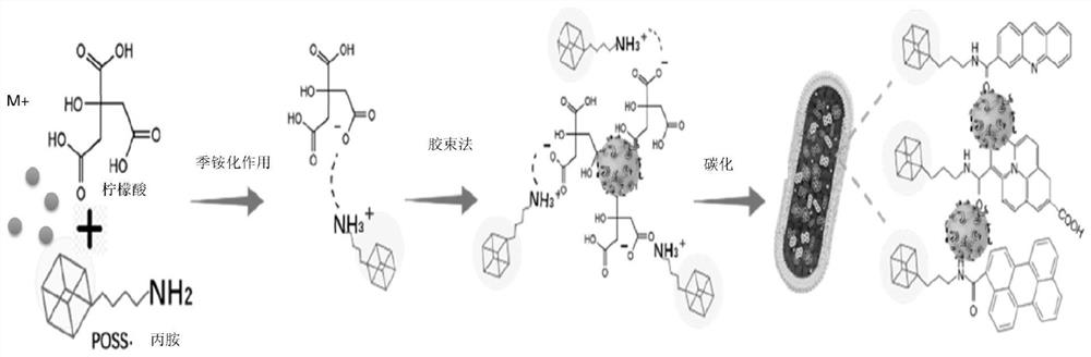
Preparation method and application of optical rotation material
A technology of optical materials and adhesive materials, applied in the direction of luminescent materials, nanotechnology for materials and surface science, chemical instruments and methods, etc., can solve problems such as loss, loss of incident light intensity, and light output rate less than 5%, and achieve Low toxicity, reduced energy consumption, good optical activity
- Summary
- Abstract
- Description
- Claims
- Application Information
AI Technical Summary
Problems solved by technology
Method used
Image

Examples
Embodiment Construction
[0023] In order to make the purpose, technical solution and advantages of the present invention clearer, the technical solution of the present invention will be clearly and completely described below in conjunction with specific embodiments of the present invention and corresponding drawings. Apparently, the described embodiments are only some of the embodiments of the present invention, but not all of them. Based on the embodiments of the present invention, all other embodiments obtained by persons of ordinary skill in the art without making creative efforts belong to the protection scope of the present invention.
[0024] The present invention will be described in further detail below in conjunction with the accompanying drawings and embodiments.
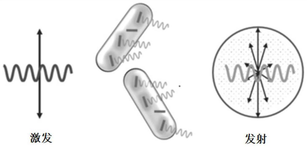
[0025] In order to improve the brightness of the LCD display, starting from the light utilization rate, the optically active material is used as the backlight luminescent material, which reduces the loss of 50% of the polarization...
PUM
 Abstract
Description
Claims
Application Information