
Cotton fines recovery device for spinning

A recovery device and fine chip technology, which is applied in the field of textile cotton fine chip recovery device, can solve the problems of easy sliding device, inability to locate, long-time manual operation, etc., and achieve the effect of flexible opening and closing and simple structure

Active Publication Date: 2022-01-28
江苏金銮纺织科技股份有限公司
View PDF14 Cites 1 Cited by
  • Summary
  • Abstract
  • Description
  • Claims
  • Application Information

AI Technical Summary

Problems solved by technology

[0005] In the present invention, a variety of working states of the base can be realized through the rotatable turning mechanism, which can not only flexibly adjust the position of the base, but also adjust the height of the base from the ground, so as to realize the opening and closing of the collection port under the base. When the drive shaft rotates At the same time, the drive shaft will drive the bottom scraper and the top gear to rotate together, the cotton fines adsorbed on the bottom filter will be gradually pushed to the outside of the bottom filter by the scraper, and the cotton fines on the side filter will rotate through the rotating cover Cleaning avoids that the bottom filter will be blocked by cotton fines when it is used for a long time and affects the effect of collecting cotton fines, and solves the problem that the cotton fines recovery device cannot be positioned and is easy to slide and the device needs to be manually operated for a long time

Method used


Image

  • Cotton fines recovery device for spinning
  • Cotton fines recovery device for spinning
  • Cotton fines recovery device for spinning

Examples


Embodiment 1

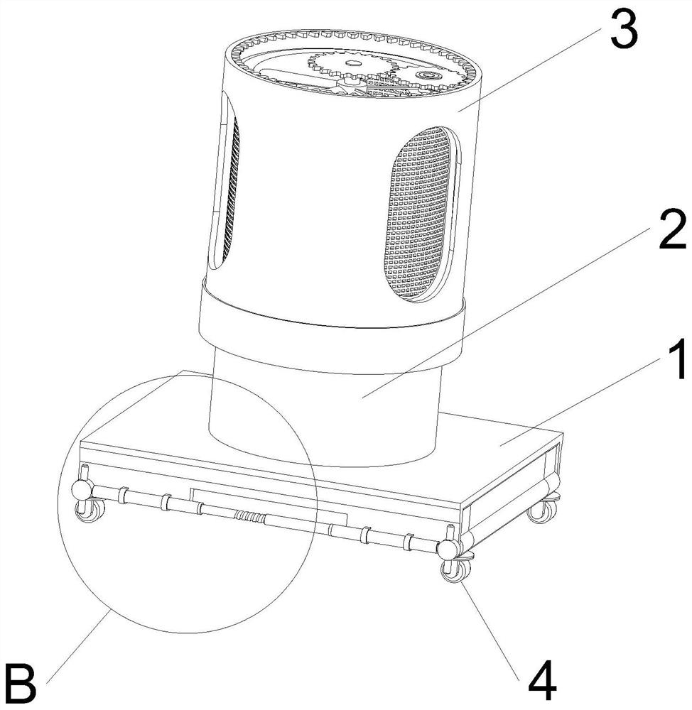
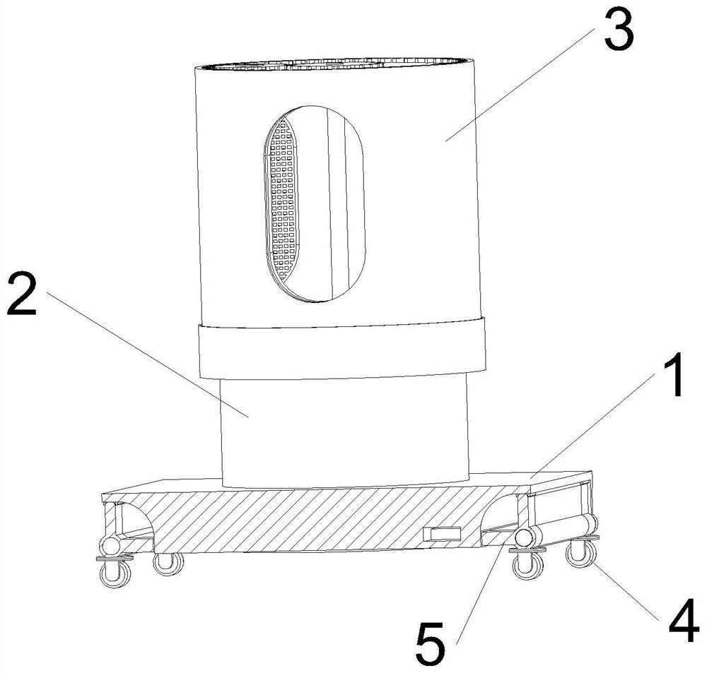
[0047] see Figure 1-Figure 6 As shown, a cotton fines recovery device for weaving includes a base 1, an air cylinder 2 is connected to the upper surface of the base 1, a rotating cover 3 is sleeved on the outer wall of the air cylinder 2, and a turning mechanism 5 is movably connected to the lower surface of the base 1 , the lower surface of the base 1 is movably connected with the universal wheel 4 through the turning mechanism 5;

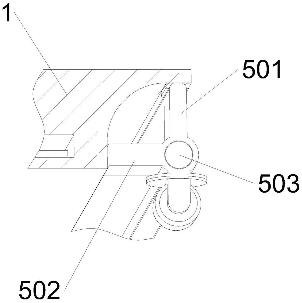
[0048] Turning mechanism 5 includes stabilizing plate 501, support plate 502, rotating shaft 503, mounting seat 504, first fixed pin 505, second fixed pin 506 and the third fixed pin 507, rotating shaft 503 is connected to base 1 two ends in rotation, rotating shaft 503 The outer wall is fixedly connected with a cylindrical tube, and the stabilizing plate 501 and the supporting plate 502 are fixedly connected to the outer wall of the cylindrical tube respectively. The stabilizing plate 501 and the supporting plate 502 are vertically arranged, and...

Embodiment 2

[0050] see Figure 7-Figure 8 As shown, a bottom filter screen 8 is installed inside the hole on the lower surface of the base 1, and the drive shaft 13 passes through the center of the bottom filter screen 8 along the vertical direction. The scraper 9 rotates on the bottom filter 8, the upper surface of the scraper 9 is close to the lower surface of the bottom filter 8, and the cotton fines adsorbed on the bottom filter 8 are gradually pushed to the outside of the bottom filter 8, and the inside of the base 1 There is a collection tank 11, which is finally pushed into the collection tank 11. The collection tank 11 is ring-shaped and sleeved on the outside of the bottom filter 8. One end of the scraper 9 is fixedly connected with a push plate 901. When the scraper 9 rotates, it drives the push plate at one end. 901 rotate together, the push plate 901 is slidably connected inside the collection tank 11, one side of the collection tank 11 is connected with the hopper 12, the cot...

Embodiment 3

[0052] see Figure 8-Figure 13 As shown, the side filter screen 17 is fixedly installed in the hole provided on the side wall of the blower 2, and the internal gear 14 is fixedly installed on the inner wall of the rotating cover 3. The internal gear 14 is located at the top of the rotating cover 3. The internal gear 14, the driving gear 15 and the transmission The gear 16 is located at the same height, and the internal gear 14, the driving gear 15 and the transmission gear 16 have the same thickness. The driving gear 15 is fixedly installed on the top of the driving shaft 13, and the driving shaft 13 rotates, driving the driving gear 15 on the top to rotate, and the top of the air duct 2 moves Connected with transmission gear 16, driving gear 15 is meshed with transmission gear 16 and connected, driving gear 15 drives transmission gear 16 to rotate when rotating, transmission gear 16 is meshed with internal gear 14 and is connected, and transmission gear 16 drives rotating cove...


PUM


Abstract

The invention relates to a cotton fines recovery technology, in particular to a cotton fines recovery device for spinning, which is used for solving the problems that a cotton fines recovery device cannot be positioned and is easy to slide and needs to be manually operated for a long time. Multiple working states of a base can be achieved through a rotatable turnover mechanism, the position of the base can be flexibly adjusted, the ground clearance of the base can be adjusted, and therefore a collecting opening below the base can be opened and closed, when the driving shaft rotates, and the driving shaft can drive a scraping strip at the bottom and a gear at the top to rotate together. Cotton fines adsorbed on a bottom filter screen are pushed by the scraping strip to be gradually pushed to the outer side of the bottom filter screen, cotton fines on the side filter screen are cleaned through rotation of a rotating cover, and the situation that the bottom filter screen is blocked by the cotton fines after being used for a long time, and the cotton fines collecting effect is affected is avoided. The problems that a cotton fines recovery device cannot be positioned and is prone to sliding and needs long-time manual operation are solved.

Description

technical field [0001] The invention relates to cotton fine scrap recovery technology, in particular to a cotton fine scrap recovery device for weaving. Background technique [0002] Cotton is the main raw material of textiles. Because textiles are a necessity of life, people will choose to plant cotton on a large scale. Correspondingly, the demand for products woven and processed from cotton will also be large. Therefore, there are many cotton processing factories with large production capacity. , but cotton often produces fine shavings during the weaving process, which are often difficult to clean due to their small size and light weight; cotton tends to stick to the broom when the fine shavings are cleaned manually, and cotton shavings are prone to flying during the cleaning process. Difficult to clean up and recycle. Cotton fines are often airborne, causing cotton fines to fall on the ground and on high machinery. Using a vacuum cleaner can easily clog internal parts. ...

Claims


Application Information

Patent Timeline
Patent Type & Authority Applications(China)
IPC IPC(8): A47L5/22A47L9/00A47L9/12A47L9/20
CPCA47L5/22A47L9/009A47L9/00A47L9/12A47L9/20
Inventor 刘渠銮刘静静位明军李亚崔北伟
Owner 江苏金銮纺织科技股份有限公司
Learn More