
A frequency reconfigurable antenna based on substrate integrated waveguide and its preparation method

A substrate-integrated waveguide and reconfigured antenna technology, which is applied to antennas, slot antennas, resonant antennas, etc., can solve problems such as the inability to realize free switching of working frequency bands, and achieve low-profile, easy-to-integrate effects

Active Publication Date: 2021-09-21
BEIHANG UNIV
View PDF4 Cites 0 Cited by
  • Summary
  • Abstract
  • Description
  • Claims
  • Application Information

AI Technical Summary

Problems solved by technology

[0003] However, the existing mainstream antennas can only realize the connection on a single frequency band. With the progress of society and the development of science and technology, people have more and more requirements for antenna work, and the accuracy requirements are becoming more and more strict. However, the existing antenna structure is large Most of them work in a single frequency band, and the free switching of the working frequency band cannot be realized

Method used


Image

  • A frequency reconfigurable antenna based on substrate integrated waveguide and its preparation method
  • A frequency reconfigurable antenna based on substrate integrated waveguide and its preparation method
  • A frequency reconfigurable antenna based on substrate integrated waveguide and its preparation method

Examples


Embodiment Construction

[0037] In order to make the purpose, technical solutions and advantages of the embodiments of the present invention clearer, the technical solutions in the embodiments of the present invention will be clearly and completely described below in conjunction with the drawings in the embodiments of the present invention. Obviously, the described embodiments It is a part of embodiments of the present invention, but not all embodiments. Based on the embodiments of the present invention, all other embodiments obtained by persons of ordinary skill in the art without creative efforts fall within the protection scope of the present invention.

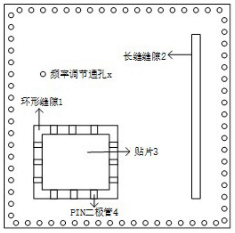
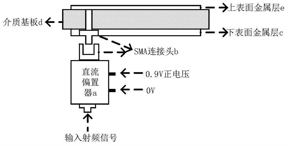
[0038] figure 1 It shows the upper surface structure diagram of a frequency reconfigurable antenna based on substrate integrated waveguide provided by an embodiment of the present invention, figure 2 It is a structure diagram of the lower surface of a frequency reconfigurable antenna based on a substrate integrated waveguide provided by an embod...


PUM

PropertyMeasurementUnit
widthaaaaaaaaaa
widthaaaaaaaaaa
dielectric lossaaaaaaaaaa

Abstract

The embodiment of the present invention discloses a frequency reconfigurable antenna based on a substrate integrated waveguide and a preparation method thereof. The antenna includes: a substrate integrated waveguide with annular slits and long slits on the upper surface; A patch is formed; multiple PIN diodes are arranged in the annular gap, and the two ends of the diodes are connected to the upper surface of the substrate integrated waveguide and the patch, and the bias state of the diode is controlled to control the connection between the patch and the substrate integrated waveguide. The upper surface is connected or disconnected; when the diode is turned on, the patch is connected to the upper surface of the substrate integrated waveguide, and radiates through the long slot on the upper surface to realize the working state of the first frequency band; when the diode is cut off, the patch It is disconnected from the upper surface of the substrate integrated waveguide, and the working state of the second frequency band is realized through the patch radiation on the upper surface. The invention can realize the switching between different bands of the antenna by controlling the bias state of the diode.

Description

technical field [0001] The invention relates to the technical field of wireless communication, in particular to a frequency reconfigurable antenna based on a substrate integrated waveguide and a preparation method thereof. Background technique [0002] In recent years, the wireless communication system is developing towards the direction of large capacity and miniaturization. While the volume of the system is further reduced, the function is further complicated, the number of wireless devices increases, and the proposal of reconfigurable antenna enables a pair of antennas to realize The function of multiple antennas is possible, which is of great significance for increasing the capacity of the communication system and reducing the weight and volume of the system. [0003] However, the existing mainstream antennas can only realize the connection on a single frequency band. With the progress of society and the development of science and technology, people have more and more re...

Claims


Application Information

Patent Timeline
Patent Type & Authority Patents(China)
IPC IPC(8): H01Q1/36H01Q9/04H01Q13/10
CPCH01Q1/36H01Q9/0464H01Q13/106
Inventor 陈爱新秦葭湄付学东孙铭宇
Owner BEIHANG UNIV
Learn More