Ultrasonic vibrator for metal drawing and drawing mechanism

An ultrasonic and vibrator technology, applied in the field of ultrasonic vibrator and drawing mechanism, can solve the problems of severe deformation, large deformation force and friction force, surface defects, etc., and achieve the goal of reducing drawing force, improving surface quality and improving fatigue resistance Effect

Pending Publication Date: 2022-01-28
CHINA INNOVATION ACADEMY OF INTELLIGENT EQUIP CO LTD +1
View PDF7 Cites 0 Cited by
  • Summary
  • Abstract
  • Description
  • Claims
  • Application Information

AI Technical Summary

Problems solved by technology

In the multi-channel drawing process, due to severe deformation, large deformation force and friction force, metal materials are prone to fracture and surface defects

Method used


Image

  • Ultrasonic vibrator for metal drawing and drawing mechanism
  • Ultrasonic vibrator for metal drawing and drawing mechanism
  • Ultrasonic vibrator for metal drawing and drawing mechanism

Examples


Embodiment 1

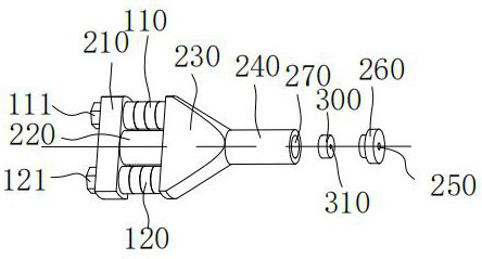
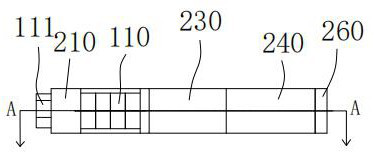
[0032] An ultrasonic vibrator, such as Figure 1 to Figure 3 shown, including: transducer and horn.

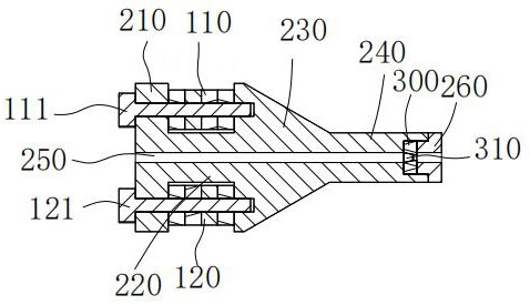
[0033] A through hole 250 is provided inside the horn, and the horn includes a base 210, a first rod body 220, a first connecting body 230 and a second rod body 240 connected sequentially from left to right; the base 210 and the first connecting body 230 A transducer is disposed between them; the transducer includes at least two piezoelectric stacks, and the vibration direction of the piezoelectric stacks is parallel to the extending direction of the through hole 250 . Preferably, the base 210 of the horn, the first rod body 220 , the first connecting body 230 and the second rod body 240 are integrally structured.

[0034] The above-mentioned ultrasonic vibrator can be set on the drawing machine as a part of the drawing machine. Preferably, the drawing die 300 can be fixed in the above-mentioned ultrasonic vibrator. The material to be drawn passes through the horn through t...

Embodiment 2

[0041] The content of this embodiment is the same as that of Embodiment 1 and will not be repeated. The difference is that: Figure 4 to Figure 6 As shown, in this embodiment, the number of piezoelectric stacks is four, which are respectively the first piezoelectric stack 110, the second piezoelectric stack 120, the third piezoelectric stack 130 and the fourth piezoelectric stack 140. A piezoelectric stack 110 , a second piezoelectric stack 120 , a third piezoelectric stack 130 and a fourth piezoelectric stack 140 are sequentially arranged around the first rod 220 at intervals of 90°. The increase in the number of piezoelectric stacks makes the vibration of the ultrasonic vibrator play a superimposed strengthening effect. It should be known that the number of piezoelectric stacks can also be set to three or five or more, and its working principle is the same as that of the present invention, and the scope of protection of the present invention includes but is not limited to th...

Embodiment 3

[0045] A pulling mechanism such as Figure 7 with Figure 8 As shown, it includes the ultrasonic vibrator, the fixing seat 400 and the mandrel 500 as described in the first embodiment; The drawing mechanism in this embodiment is used for drawing the pipe, the pipe to be drawn is inserted into the through hole 250, the mandrel 500 is placed in the core of the pipe to be drawn, and the drawing pliers pull the pipe to be drawn toward the end of the gland 260. Moving to the right, the pipe to be drawn passes through the drawing hole 310, and under the extrusion of the drawing die 300, the outer diameter of the pipe to be drawn is reduced. During the whole drawing process, the ultrasonic vibrator drives the drawing die 300 to vibrate at the same frequency. According to different drawing procedures, the state of linear vibration and torsional vibration can be selected.

[0046] Further, an ultrasonic vibrator is arranged on the fixing seat 400 . The ultrasonic vibrator here drive...


PUM


Abstract

The invention provides an ultrasonic vibrator for metal drawing and a drawing mechanism, and relates to the technical field of metal drawing. The ultrasonic vibrator comprises a transducer and an amplitude-change pole; a penetrating through hole is formed in the amplitude-change pole; the amplitude-change pole comprises a base, a first pole body, a first connecting body and a second pole body which are sequentially connected from left to right; the transducer is arranged between the base and the first connecting body; the transducer comprises at least two piezoelectric stacks, and the vibration direction of the piezoelectric stacks is parallel to the extension direction of the through hole. Vibration of the ultrasonic vibrator is added in the drawing process, so that when material to be drawn passes through a drawing die, the friction characteristic is changed, the material is softened, the drawing force can be remarkably reduced, the abrasion of the drawing die is reduced, and the drawing efficiency and the yield are improved. The ultrasonic vibrator has a plurality of working states which are respectively suitable for different drawing procedures.

Description

technical field [0001] The invention relates to the field of metal drawing, in particular to an ultrasonic vibrator and a drawing mechanism for metal drawing. Background technique [0002] Drawing products mainly include wire and pipe, which are widely used in various industries, such as various metal pipe products, metal wire, welding wire and other products. The drawn product is mainly produced by a drawing machine. The material to be drawn is placed in the drawing mold, and the material to be drawn is pulled by external force with the drawing pliers until the required drawn product is formed. The drawing processing of conventional metals requires multiple drawing processes to complete. In the multi-channel drawing process, due to severe deformation, large deformation force and friction force, metal materials are prone to fracture and surface defects. How to effectively solve the problem of surface defects of drawn products and improve the surface quality of drawn produc...

Claims


Application Information

Patent Timeline
IPC IPC(8): B06B1/06B21C1/02
CPCB06B1/06B21C1/02
Inventor 罗灵杰张雷李群龙伟民赵波
Owner CHINA INNOVATION ACADEMY OF INTELLIGENT EQUIP CO LTD
Why Eureka
Try Eureka