Saw cutting center based on multiple angles of 45-90 degrees

A multi-angle, sawing technology, which is applied in the direction of metal sawing equipment, sawing machine, metal processing equipment, etc., can solve the problems of low sawing efficiency, labor loss, waste of time, etc., achieve low production cost and speed up sawing , high efficiency effect

Active Publication Date: 2022-01-28
广东联仝智能机械有限公司
View PDF6 Cites 0 Cited by
  • Summary
  • Abstract
  • Description
  • Claims
  • Application Information

AI Technical Summary

Problems solved by technology

[0003] Aluminum alloy profiles have been widely used in aviation, aerospace, automobile, machinery manufacturing, shipbuilding, construction, decoration, and chemical industries. With the rapid development of the economy, the demand for aluminum alloy welded structural parts is increasing, so that the research on the weldability of aluminum alloys is also in-depth. When aluminum alloy profiles are processed, due to their diverse shapes and structures, cutting There are many requirements for the angle of the knife. Usually, one sawing center only corresponds to one sawing shape. If two or more sawing shapes are required, the cooperation of multiple machines is required, although the required However, the sawing efficiency is low and the cost is too high. Workers are required to cooperate when switching sawing machines, which not only wastes time, but also causes serious labor loss. The cooperation of multiple machines also expands the production area, which is very important for The increasing demand for aluminum alloy profile processing technology is unfavorable. Therefore, it is necessary to study a sawing machine for aluminum alloy profiles that can be converted from multiple angles.

Method used


Image

  • Saw cutting center based on multiple angles of 45-90 degrees
  • Saw cutting center based on multiple angles of 45-90 degrees
  • Saw cutting center based on multiple angles of 45-90 degrees

Examples


Embodiment 1

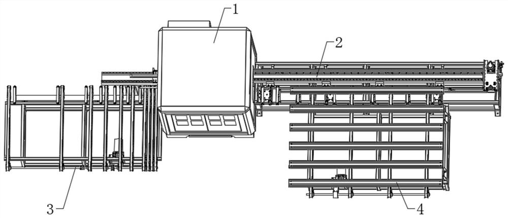
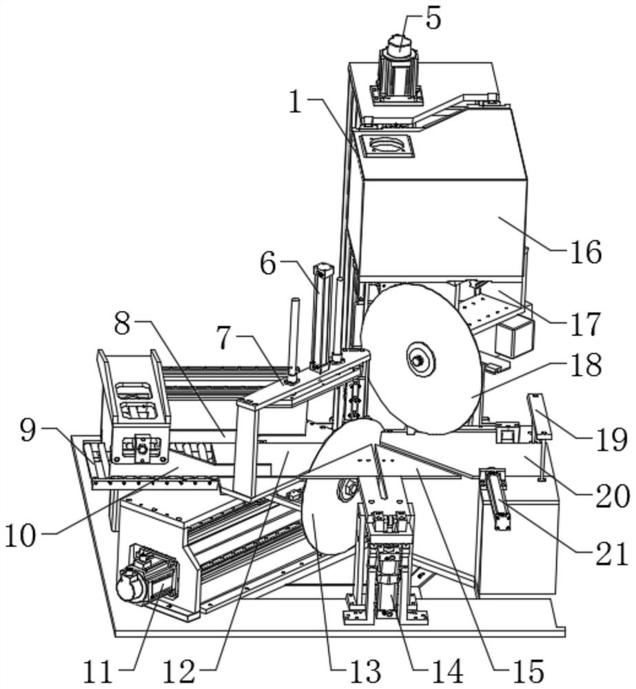
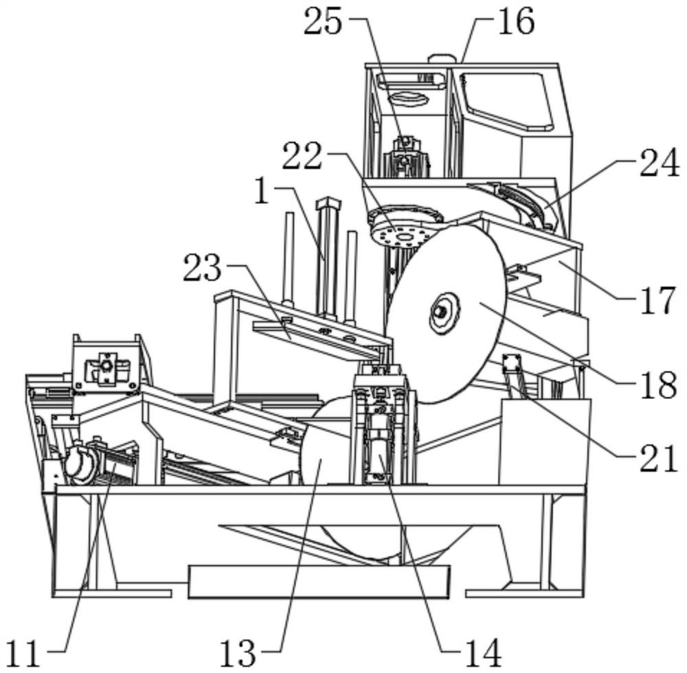
[0031] see Figures 1 to 5 , the present invention provides a technical solution: a multi-angle sawing center based on 45° to 90°, including a profile sawing center 1, the two sides of the profile sawing center 1 are respectively provided with a feed center 4 for feeding and a In the discharge center 3 of the discharge, the feed center 4 is provided with a feed center 2 for transporting profiles into the profile sawing center 1. The profile sawing center 1 includes a sawing table 16, and the sawing table 16 is equipped with a The reversing motor 25 of reversing conversion, the reversing motor 25 output end is provided with the reversing rotating plate 22 that cooperates with sawing platform 16 rotations, and reversing rotating plate 22 one sides is fixed with reversing bracket 17, and reversing bracket 17 is set There is a direction-changing track 24 that slides with the direction-changing bracket 1 and is fixed at the bottom of the sawing table 16. The direction-changing brac...


PUM


Abstract

The invention relates to the field of aluminum alloy profile machining, and particularly discloses a saw cutting center based on multiple angles of 45-90 degrees. The saw cutting center based on multiple angles of 45-90 degrees comprises a profile saw cutting center, a feeding center and a discharging center are arranged on the two sides of the profile saw cutting center respectively, a mateiral sending center is arranged at the feeding center, the profile saw cutting center comprises a saw cutting table, a turning motor is installed on the saw cutting table, and a turning rotating plate is arranged at the output end of the turning motor; a turning support is fixed to one side of the turning rotating plate, the turning support is provided with a turning rail which is in sliding fit with the turning support and fixed to the bottom of the sawing table, and the turning support is provided with a turning sawing cutter which is in rotating fit with the turning support and used for sawing the profile. By changing the saw cutting angle of the saw cutter, the profile can be saw-cut at a time during cutting and does not need to be repeatedly moved to a plurality of saw cutting machines, so that the saw cutting efficiency is improved, the saw cutting speed is increased, and the section angle of theprofile is accurate and high in efficiency.

Description

technical field [0001] The invention relates to the field of processing aluminum alloy profiles, in particular to the multi-angle sawing technology of aluminum alloy profiles. Background technique [0002] Profiles refer to solid straight strips that have been formed by plastic processing and have a certain cross-sectional shape and size. There are many varieties and specifications of profiles, and they are widely used. The shape has certain mechanical and physical properties. The profile can be used alone or further processed into other manufactured products. It is often used in building structures and manufacturing installations. Mechanical engineers can choose the specific shape, material, heat treatment state, and mechanical properties of the profile according to the design requirements. and other parameters, and then divide the profile according to the specific size and shape requirements, and then further process or heat treatment to meet the design accuracy requiremen...

Claims


Application Information

Patent Timeline
Patent Type & Authority Applications(China)
IPC IPC(8): B23D45/10B23D45/02B23D47/02B23D47/04B23D47/10
CPCB23D45/10B23D45/024B23D47/04B23D47/02B23D47/10
Inventor 向军邓智军
Owner 广东联仝智能机械有限公司
Why Eureka
Try Eureka