
Slicing machine

A technology of slicing machine and cutting room, which is applied to fine working devices, stone processing equipment, manufacturing tools, etc., can solve problems such as high risk factor and limited operating space for personnel, and achieve the effect of reducing volume and weight

Pending Publication Date: 2022-01-28
DALIAN LIANCHENG NUMERICAL CONTROL MACHINE
View PDF0 Cites 0 Cited by
  • Summary
  • Abstract
  • Description
  • Claims
  • Application Information

AI Technical Summary

Problems solved by technology

[0002] The slicer uses a diamond wire to cut silicon rods, and cuts the silicon rods into silicon wafers. However, the current slicers all use the front-end feeding method, and most of the manual operations of the slicer are performed at the front end of the machine tool.
When realizing the automation project, the front-end loading automation equipment area overlaps with the manual operation area, the operating space for personnel is limited, and the risk factor is high

Method used


Image

  • Slicing machine
  • Slicing machine
  • Slicing machine

Examples


Embodiment Construction

[0060] It should be noted that, in the case of no conflict, the embodiments of the present invention and the features in the embodiments can be combined with each other. The present invention will be described in detail below with reference to the accompanying drawings and examples.

[0061] In order to make the purpose, technical solutions and advantages of the embodiments of the present invention clearer, the technical solutions in the embodiments of the present invention will be clearly and completely described below in conjunction with the drawings in the embodiments of the present invention. Obviously, the described embodiments It is only some embodiments of the present invention, but not all embodiments. The following description of at least one exemplary embodiment is merely illustrative in nature and in no way taken as limiting the invention, its application or uses. Based on the embodiments of the present invention, all other embodiments obtained by persons of ordina...


PUM

PropertyMeasurementUnit
diameteraaaaaaaaaa

Abstract

The invention provides a slicing machine. The slicing machine comprises a machine body; a cutting chamber which is positioned on the front side of a lathe bed; a rear end feeding channel which is located in the middle of the rear side of the lathe bed; an accompanying AGV bracket which is located in the rear end feeding channel and used for carrying a silicon rod; a cross beam which is horizontally mounted at the top end of the cutting chamber; a vertical feeding device which is fixedly connected with the cross beam, wherein the output end of the vertical feeding device is located in the cutting chamber; a clamp device which is connected with the output end of the vertical feeding device and used for clamping the silicon rod consigned by the accompanying AGV bracket; and a line cutting mechanism which is positioned in the cutting chamber and is used for cutting the silicon rod into a plurality of silicon wafers. Rear-end feeding can be achieved, the rear-end feeding is separated from a manual operation area, the manual operation space is large and convenient, and the personnel safety is greatly improved.

Description

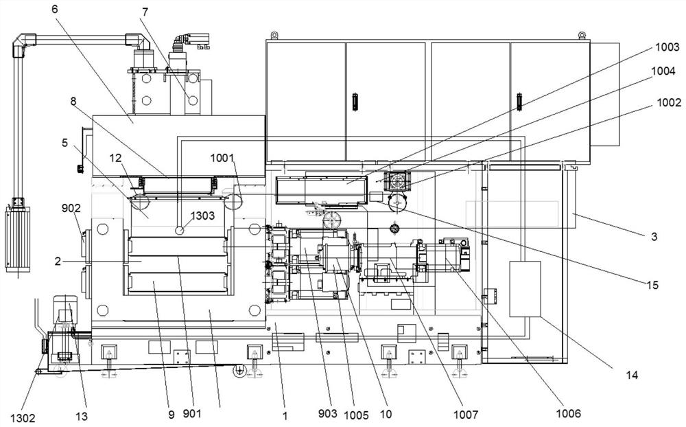
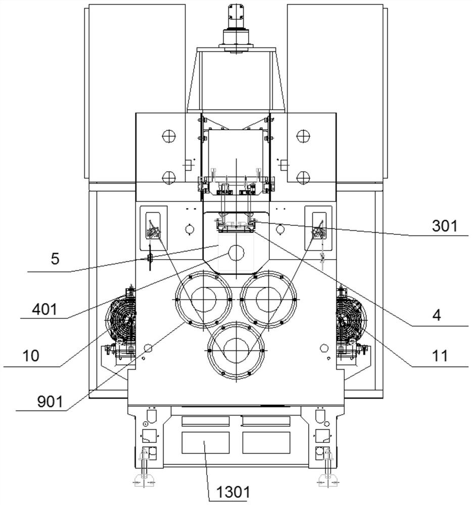
technical field [0001] The invention relates to the technical field of silicon rod cutting, in particular to a slicer. Background technique [0002] Slicers use diamond wires to cut silicon rods and cut silicon rods into silicon wafers. However, the current slicers all use front-end feeding, and most of the manual operations of the slicer are performed at the front end of the machine tool. When realizing the automation project, the front-end loading automation equipment area overlaps with the manual operation area, the operating space for personnel is limited, and the risk factor is high. Contents of the invention [0003] According to the above technical problem, a slicer is provided. [0004] The technical means adopted in the present invention are as follows: [0005] A slicer comprising: [0006] bed frame; [0007] cutting chamber, located at the front side of the bed; [0008] The rear end feeding channel is located in the middle of the rear side of the bed, its...

Claims


Application Information

Patent Timeline
Patent Type & Authority Applications(China)
IPC IPC(8): B28D5/00B28D5/04
CPCB28D5/045B28D5/0058B28D5/0076B28D5/0082
Inventor 刘秀坤许博姜阳白雪情张树礼刘丽娟
Owner DALIAN LIANCHENG NUMERICAL CONTROL MACHINE
Learn More