Transfer box for electronic special materials

A transfer box, electronic technology, applied in the direction of transportation and packaging, rigid containers, containers to prevent mechanical damage, etc., to achieve the effect of reducing space occupation, convenient storage and transportation

Pending Publication Date: 2022-01-28
苏州华佑信息科技有限公司
View PDF13 Cites 0 Cited by
  • Summary
  • Abstract
  • Description
  • Claims
  • Application Information

AI Technical Summary

Problems solved by technology

[0007] Aiming at the deficiencies of the prior art, the present invention provides a transfer box for electronic special materials, which solves the problems mentioned in the prior art

Method used


Image

  • Transfer box for electronic special materials
  • Transfer box for electronic special materials
  • Transfer box for electronic special materials

Examples


Embodiment 1

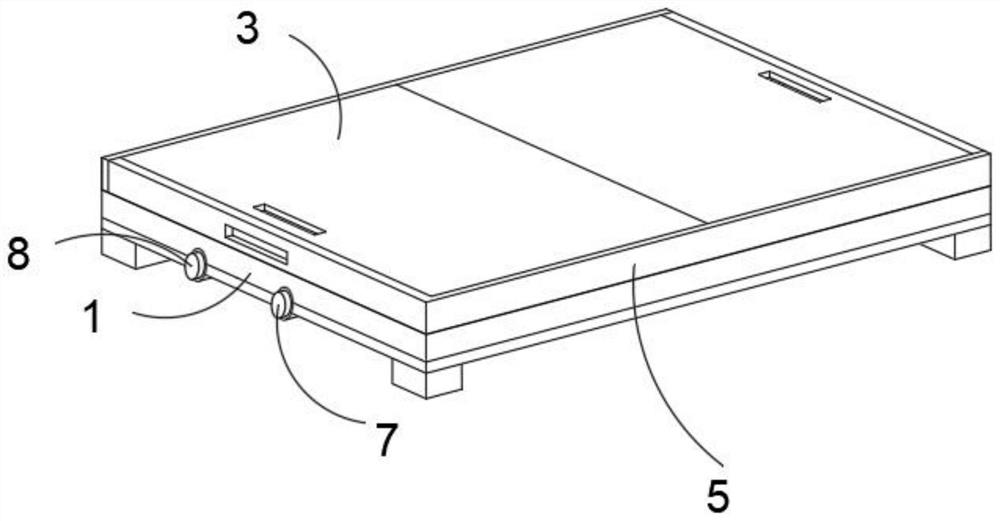
[0037] This embodiment provides the specific structure of the cover assembly, such as Figure 1-3 As shown, an air pump assembly is installed on the side of the base 1, and the air pump assembly is used to inflate and deflate the bag main body 4;

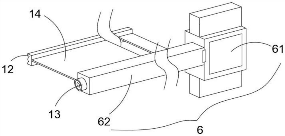
[0038] Both sides of the inner wall of the top frame 5 are provided with a cover assembly 6, and the cover assembly 6 includes a sliding piece 61 and a folding rod 62 connected to one side of the sliding piece 61 through a rotating shaft, and the folding rod 62 is turned inwardly and equipped with a torsion spring The rotating shaft part 13, the surface of this rotating rod is wound with the winding film 14 that is used to cover the opening above the top frame 5;

[0039] When the above-mentioned cover assembly 6 is specifically used:

[0040] Flip the folding rod 62 by 90° so that two groups of folding rods 62 are distributed parallel to each other, slide the slider 61 close to the position of the side flap 3, then hold the magnet...

Embodiment 2

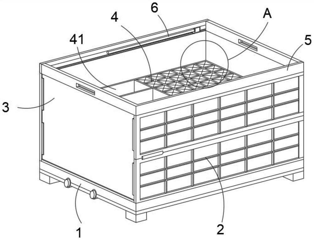
[0050] This embodiment provides the specific structure of the front flap and the side flap, as figure 1 As shown, the front flap 2 includes two groups of flaps, and the adjacent flaps, between the flaps and the top frame 5, and between the flaps and the base 1 are all connected by rotating shafts. A retaining strip for blocking the side flap 3 is provided.

[0051] refer to image 3 As shown, the turning angle of the side flap 3 is 0-90°, and the area where the side flap 3 turns over is located in the inner cavity of the transfer box, and the unfolded front flap 2 is always vertically distributed with the side flap 3 .

[0052] Specifically, when packing the entire transfer box:

[0053] Shrink the bag main body 4 so that there is room for the side flap 3 to turn inwards,

[0054]Then, the side turning plate 3 is turned inward, and the entire top frame 5 is pressed down.

[0055] By adopting the above technical solutions:

[0056] The present invention adopts a folding tr...

Embodiment 3

[0058] This embodiment provides the specific structure of the bag body. The bag body 4 is arranged on the upper surface of the base 1, and one side of the bag body 4 is provided with a side bag body 41. the partitioning capsule 15 of the region;

[0059] refer to Figure 4 As shown, the upper part of the bag main body 4 is provided with several bag openings with a rectangular section, and the opening end of each bag opening is provided with a cover sheet group 11 for closing the bag opening;

[0060] Each of the above pockets can be filled with special electronic materials;

[0061] The above-mentioned cover page set 11 adopts four pieces of triangular-shaped films, and forms a rectangular structure, which is used to close the opening ends of each pocket opening. After putting the electronic special materials to be loaded into the corresponding pocket openings, each film returns to its original state. , so as to realize the function of closed processing.

[0062] refer to ...


PUM


Abstract

The invention discloses a transfer box for electronic special materials, the transfer box comprises a base, a top frame distributed right above the base, a front folding plate and a side turning plate used for connecting the base and the top frame, and a bag main body assembled in the transfer box, the side of the base is provided with an air pump assembly, and the air pump assembly is used for inflating and deflating the bag main body; sealing cover assemblies are arranged on the two sides of the inner wall of the top frame. According to the technical scheme, the foldable transfer box is adopted, when the foldable transfer box needs to be used, corresponding front folding plates and side turning plates can be turned over, so that the base and the top frame are attached to each other, a plate-shaped structure is formed, the occupied space is reduced, and storage and transportation treatment are facilitated; the sealing cover assembly is arranged on the inner wall side of the top frame, after the whole transfer box is completely unfolded, a rolling film is pulled out, magnetic attraction type connection is conducted through the magnetic strip, cover sealing treatment on the whole transfer box can be completed, and meanwhile normal use of the transfer box cannot be affected when the whole sealing cover assembly is not used.

Description

technical field [0001] The invention belongs to the technical field of transfer boxes, in particular to a transfer box for electronic special materials. Background technique [0002] As a kind of storage box, the transfer box can accommodate and transfer many types, such as: medical boxes used for transferring medical equipment, garbage bins used for transferring garbage, turnover boxes used in logistics parks, and electronic special Special transfer box for material transfer; [0003] However, the existing cabinets have a simple structure and are basically made of different materials. At the same time, the specifications of the cabinets are fixed and cannot be adjusted or changed. The following technical problems will occur during specific use: [0004] First, there is only one cavity inside the traditional transfer box for electronic materials. After many parts are accumulated in the transfer box, they will collide with each other during the transfer process, resulting in...

Claims


Application Information

Patent Timeline
IPC IPC(8): B65D6/18B65D13/00B65D25/02B65D25/10B65D43/20B65D81/05B65D85/00
CPCB65D7/06B65D7/26B65D9/06B65D9/14B65D11/1833B65D11/20B65D9/32B65D7/42B65D13/00B65D25/02B65D25/101B65D43/20B65D81/05B65D85/70
Inventor 赵威王扬
Owner 苏州华佑信息科技有限公司
Why Eureka
Try Eureka