Colorful graphical color-changing fabric based on electronic ink and preparation method

An electronic ink, color graphics technology, applied in chemical instruments and methods, fabrics, woven fabrics, etc., can solve the problems of inability to integrate, the fabric does not have flexibility, etc., achieve high color stability, rich secondary development potential, etc. The effect of wide application prospects

Active Publication Date: 2022-01-28
SOUTHEAST UNIV
View PDF8 Cites 0 Cited by
  • Summary
  • Abstract
  • Description
  • Claims
  • Application Information

AI Technical Summary

Problems solved by technology

[0005] Chinese patent application number 2010101365461 discloses a color-changing camouflage fabric based on electronic ink display technology and its preparation method, although more than two camouflage patterns on the surface of the

Method used


Image

  • Colorful graphical color-changing fabric based on electronic ink and preparation method
  • Colorful graphical color-changing fabric based on electronic ink and preparation method
  • Colorful graphical color-changing fabric based on electronic ink and preparation method

Examples


Embodiment 1

[0036] (1) The conductive yarn and insulating yarn are woven into a double-layer conductive fabric microstrip with a width of 12mm by double-layer warp knitting process. The edge is composed of insulating yarn, and the center surface is composed of conductive yarn. Silver conductive yarn, insulating yarn is 70D24F nylon yarn, and the conductive yarn is woven into the central area of ​​the microstrip. The width of the conductive area is about 10mm, the width of the side layers on both sides is about 1mm, and the square resistance of the conductive microstrip is ~1Ω.

[0037] (2) Coil the woven continuous strip and import it into the rubber scraping machine. A number of microstrips are arranged in parallel, and each is equipped with a dispensing head, and the electronic ink microcapsule slurry and water-based polyurethane mixed slurry are dripped on the microstrips. In the center of the conductive area, the electronic ink is an electrophoretic microcapsule slurry with a density o...

Embodiment 2

[0042] (1) The conductive yarn and insulating yarn are woven into a double-layer conductive fabric microstrip with a width of 12mm by double-layer warp knitting process. The edge is composed of insulating yarn, and the center surface is composed of conductive yarn. Silver conductive yarn, polyester yarn 75D72F is used as the insulating yarn, and the conductive yarn is woven into the central area of ​​the microstrip. The width of the conductive area is about 10mm, and the width of the side layers on both sides is about 1mm. After the microstrip is woven, the conductive area is plated with silver, and the thickness is about 2μm , The square resistance of the conductive microstrip is ~1Ω.

[0043] (2) Coil the woven continuous strip and import it into the rubber scraping machine. A number of microstrips are arranged in parallel, and each is equipped with a dispensing head, and the electronic ink microcapsule slurry and water-based polyurethane mixed slurry are dripped on the micro...

Embodiment 3

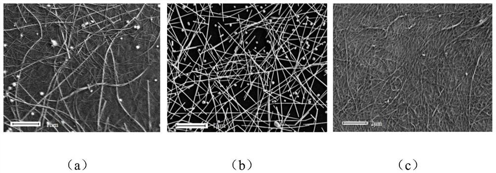
[0048] (1) The conductive yarn and the insulating yarn are woven into a double-layer conductive fabric microstrip with a width of 12 mm by double-layer warp knitting technology. The edge is composed of insulating yarn, and the center surface is composed of conductive yarn. Material-coated conductive yarn, the nanomaterials in the conductive yarn coating are carbon nanotubes and silver nanowires, the specification is 75D3F, the insulating yarn is polypropylene yarn, the specification is 75D36F, and the conductive yarn is woven into the microstrip by high-density knitting technology In the central area, the width of the conductive area is about 10 mm, the width of the side layers on both sides is about 1 mm, and the square resistance of the conductive microstrip is ~1Ω.

[0049] (2) After the woven continuous strip is coiled, it is introduced into the rubber scraping machine, and several microstrips are arranged in parallel, and each is provided with a dispensing head, and the el...


PUM

PropertyMeasurementUnit
The average diameteraaaaaaaaaa
Densityaaaaaaaaaa
Thicknessaaaaaaaaaa

Abstract

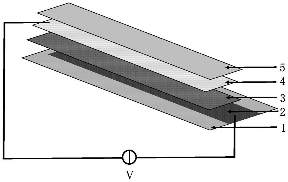
The invention discloses a color graphical color-changing fabric based on electronic ink and a preparation method, the fabric comprises a conductive fabric micro-strip formed by weaving conductive yarns and insulating yarns, the conductive yarns form a conductive area, and the insulating yarns form an insulating area; an electronic ink microcapsule layer is arranged on the conductive region; a flexible transparent conductive layer is arranged on the electronic ink microcapsule layer; and a transparent polymer layer is arranged on the flexible transparent conductive layer. The surface layer of the micro-strip is a conductive layer, the bottom layer of the micro-strip is an insulating layer, the electrophoretic discoloration micro-capsule, the conductive one-dimensional nano-material and the transparent polymer are uniformly coated on the surface of the micro-strip, and the voltage outputted by the driving circuit is respectively applied to the conductive micro-strip and the transparent conductive layer, so that the selective turning color development of the centimeter-scale micro-area on the surface of the micro-strip is realized. The upper electrode and the lower electrode are connected with a control circuit, centimeter-size pixel control and large-size graph display are achieved, and the foldable, high-environment-tolerance, low-cost and large-area color display and self-adaptive visible light camouflage fabric based on the conductive fabric base material is manufactured.

Description

technical field [0001] The invention belongs to self-adaptive visible light color rendering fabric, in particular to an adaptive visible light color rendering fabric based on electronic ink and a preparation method. Background technique [0002] Functional fibers formed by endowing fiber materials with new properties can be used to prepare smart fabrics, among which color-changing fabrics provide a broad development space for large-scale dynamic graphics and text display, color-changing clothing, camouflage clothing, and weaponry camouflage cloth. [0003] Electronic ink display components have certain market advantages due to their low power consumption and high visibility under strong light, but their high price and low contrast limit their application scenarios. The use of conductive fabric as a substrate gives electronic ink new application opportunities, especially In low cost, large area display and dynamic camouflage scenarios. At present, the electronic ink display ...

Claims


Application Information

Patent Timeline
IPC IPC(8): D04B21/08D03D11/00D03D15/533D03D15/50D03D1/00B32B27/34B32B27/36B32B27/32B32B27/02B32B27/12B32B5/02B32B33/00B32B37/00B32B38/00B32B38/16
CPCD04B21/08D03D11/00D03D15/533D03D15/50D03D1/0094D03D1/0047D03D1/0088B32B5/02B32B5/26B32B33/00B32B37/00B32B38/164B32B38/00D10B2403/02421D10B2403/02431B32B2037/243B32B2038/0076B32B2250/20B32B2262/0261B32B2262/0276B32B2262/0253B32B2255/02B32B2307/4023B32B2307/7265
Inventor 尹超逸刘瑞芳巴龙
Owner SOUTHEAST UNIV
Why Eureka
Try Eureka