
Power-assisted pipeline valve

A pipeline valve and power-assisted technology, which is applied to valve details, safety valves, balance valves, etc., can solve problems that affect the service life of valves, easily cause water hammer effects, and damage valves and pipelines, so as to reduce operating labor and water hammer. Good prevention and control effect, avoiding the effect of line loss

Pending Publication Date: 2022-01-28
HAINAN NUCLEAR POWER CO LTD
View PDF0 Cites 3 Cited by
  • Summary
  • Abstract
  • Description
  • Claims
  • Application Information

AI Technical Summary

Problems solved by technology

However, most nuclear power plants use manual valves, mainly through manual operation of the valve to control the switch of the valve. However, the following problems exist in the current use process: 1. In order to ensure the sealing of the valve, the relevant connecting parts of the valve are all Tight fit, so when opening and closing the valve, if the strength is small, it often takes a lot of effort, and even needs to find auxiliary tools or helpers to realize the opening and closing of the valve, especially the performance of relatively large valves is more obvious; 2 , When the valve is closed suddenly, it is easy to cause the water hammer effect, and the water hammer cannot be effectively alleviated, which seriously affects the service life of the valve, and may even directly cause damage to the valve and the pipeline

Method used


Image

  • Power-assisted pipeline valve
  • Power-assisted pipeline valve
  • Power-assisted pipeline valve

Examples


Embodiment Construction

[0027] In order to better understand the technical content of the present invention, specific embodiments are provided below, and the present invention is further described in conjunction with the accompanying drawings.

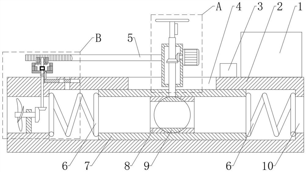
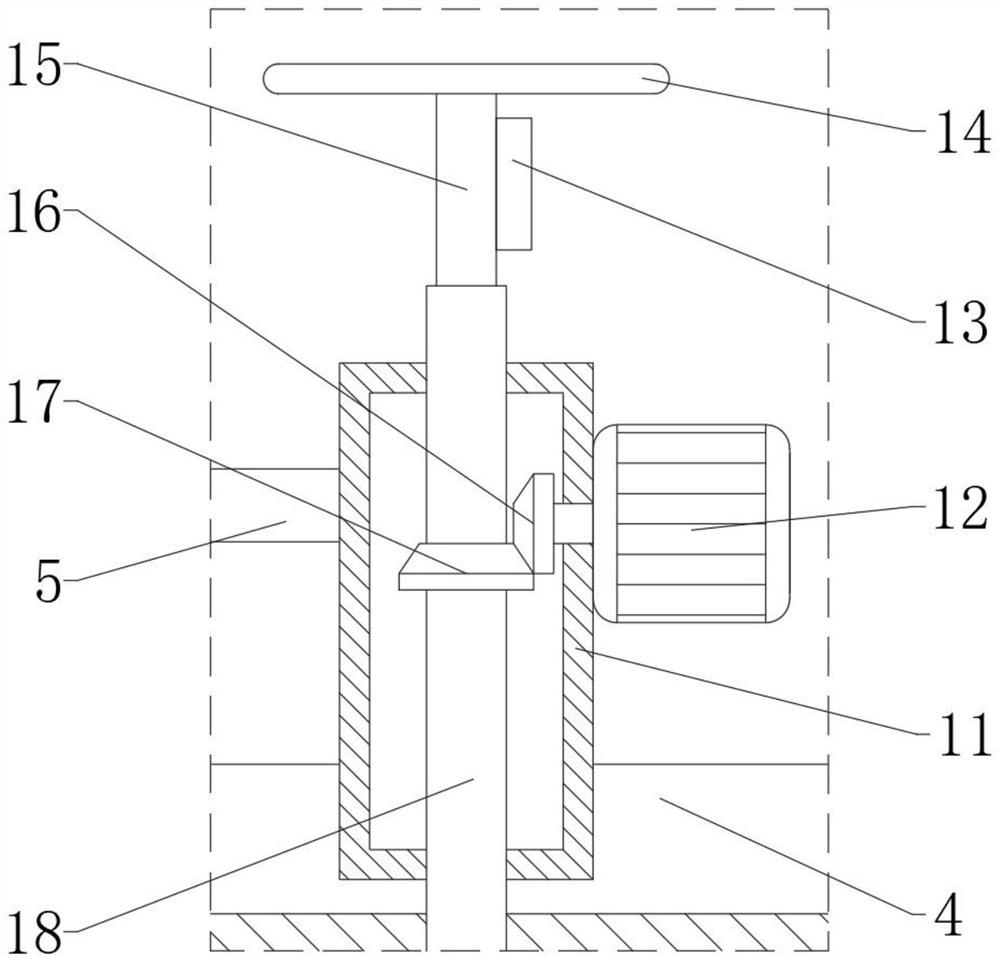
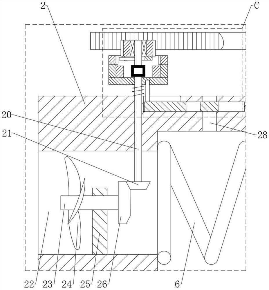
[0028] see Figures 1 to 9 , the present invention provides a power-assisted pipeline valve, which includes a valve body 2 and a pressure relief assembly. The left and right sides of the valve body 2 are respectively provided with a water inlet 22 and a water outlet 10, and the valve is connected to the pipeline through the water inlet 22 and the water outlet 10. , the top of the valve body 2 is provided with a first chute 4, the valve body 2 is slidingly provided with a sliding sleeve 7, both sides of the sliding sleeve 7 are connected with the inner wall of the valve body 2 through the first spring 6, and a ball valve is arranged inside the sliding sleeve 7 Assemblies, the ball valve assembly is used to conduct and block the water flow, the valve stem 18 is...


PUM


Abstract

The invention relates to a power-assisted pipeline valve which comprises a valve body and a pressure relief assembly, a first sliding groove is formed in the top of the valve body, a sliding sleeve is arranged in the valve body, the two sides of the sliding sleeve are connected with the inner wall of the valve body through first springs, a ball valve assembly is arranged in the sliding sleeve, a valve rod is connected to the ball valve assembly, the valve rod penetrates out of the sliding sleeve and is sleeved with a sliding shell, and the sliding shell is arranged in the first sliding groove. An electric power-assisted mechanism and a rack are arranged on the sliding shell, the electric power-assisted mechanism is connected with the valve rod, a first rotating shaft is arranged on the valve body in a penetrating mode, a fifth gear, a rotating disc and a third spring are sequentially arranged on the first rotating shaft from top to bottom, the fifth gear is meshed with the rack, the rotating disc is connected with the fifth gear through a centrifugal locking mechanism, the third spring is connected with the rotating disc and the valve body, and the pressure relief assembly is arranged on the valve body and connected with the rotating disc. The problems that in the prior art, the manual valve is strenuous to operate for people with small strength, the water hammer control effect is poor, and the service life of the manual valve is seriously affected are effectively solved.

Description

technical field [0001] The invention belongs to the technical field of valves, in particular to a power-assisted pipeline valve. Background technique [0002] A large number of liquid delivery pipelines need to be installed in nuclear power plants for production and operation, the most representative of which is water delivery pipelines, and multiple valves need to be installed on the pipelines to control the on-off of water flow transmission. However, most nuclear power plants use manual valves, mainly through manual operation of the valve to control the switch of the valve. However, the following problems exist in the current use process: 1. In order to ensure the sealing of the valve, the relevant connecting parts of the valve are all Tight fit, so when opening and closing the valve, if the strength is small, it often takes a lot of effort, and even needs to find auxiliary tools or helpers to realize the opening and closing of the valve, especially the performance of rela...

Claims


Application Information

Patent Timeline
Patent Type & Authority Applications(China)
IPC IPC(8): F16K5/06F16K5/08F16K5/10F16K17/164F16K17/168F16K27/06F16K27/04F16K31/05F16K31/53F16K31/54F16K47/02F03B13/00H02J7/14
CPCF16K5/06F16K5/0647F16K5/08F16K5/10F16K17/164F16K17/168F16K27/067F16K27/044F16K31/055F16K31/535F16K31/54F16K47/023F03B13/00H02J7/14F05B2220/706F16K31/046F16K5/0605F16K47/02F16K47/045
Inventor 王彤臣张军吴明星刘晓龙朱建斌李若鲲鲍宇汤利专于景志李恒敬
Owner HAINAN NUCLEAR POWER CO LTD
Learn More