Heat exchange roller with multi-layer built-in flow channels and working method thereof

A technology of flow channel and spiral flow channel is applied in the field of heat exchange rollers with multi-layer built-in flow channels, which can solve the problem of large heating or cooling effect at the liquid inlet, overheating or subcooling of the liquid inlet and outlet, and film product quality. To improve the quality of film products, good temperature uniformity, and increased strength

Pending Publication Date: 2022-01-28
宣城市雍基超镜面精密机械制造有限公司
View PDF0 Cites 0 Cited by
  • Summary
  • Abstract
  • Description
  • Claims
  • Application Information

AI Technical Summary

Problems solved by technology

However, this heat exchange roller has the problem of local overheating or supercooling. This is because when the heat exchange fluid enters from the liquid inlet, it is relatively hot or cold, which has a great heating or cooling effect on the liquid inlet, resulting in Too hot or too cold at the port and outlet
In actual production, it is often necessary to leave margins at both ends of the heat exchange roller, and the distance between the margins is about 200mm, so that the ends near the liqu

Method used


Image

  • Heat exchange roller with multi-layer built-in flow channels and working method thereof
  • Heat exchange roller with multi-layer built-in flow channels and working method thereof
  • Heat exchange roller with multi-layer built-in flow channels and working method thereof

Examples


Example Embodiment

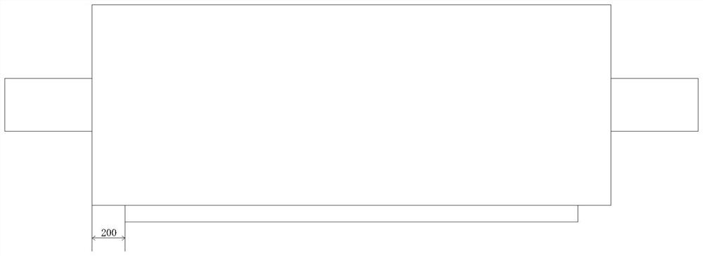
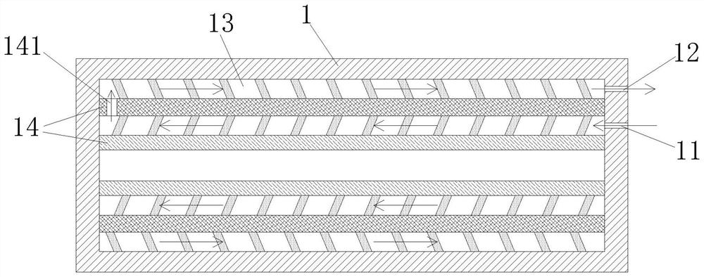
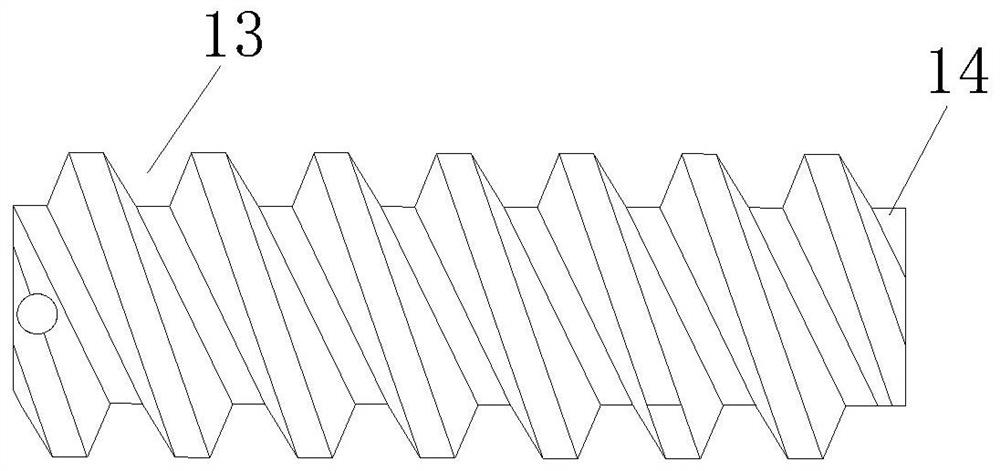
[0016] Example 1, see figure 1 , figure 2 as well as image 3 The heat exchange roller of the multilayer built-in flow channel includes a roller body 1; an inlet 11 and a liquid opening 12 are provided on the roller body 1; at least two flow channels 13 are disposed inside the roller body 1; at least Two of the flow paths 13 are disposed inwardly; at least two of the flow paths 13 communicate with each other; the innermost flow path 13 and the inlet 11 are in communication; outermost side The flow path 13 is in communication with the liquid opening 12;

[0017] The inlet 11 → at least two flow paths 13 → the liquid opening 12 forms a liquid passage into the liquid passage, so that the heat exchange fluid is gradually flowing in the direction of the roller wall, which is the advantage of this flow mode : On the one hand, by the heat transfer fluid flows from the inside to the direction near the roller wall, the heat exchange heat exchange heat and the heat exchange is gradually diff...


PUM


Abstract

The invention discloses a heat exchange roller with multi-layer built-in flow channels. The heat exchange roller comprises a roller body; a liquid inlet and a liquid outlet are formed in the roller body; at least two flow channels are arranged in the roller body; the at least two flow channels are sequentially arranged from inside to outside; the at least two flow channels are communicated with each other to form a liquid channel from inside to outside; the flow channel on the innermost side is communicated with the liquid inlet; and the flow channel on the outermost side is communicated with the liquid outlet. On one hand, heat exchange liquid gradually flows towards the roller wall from inside, heat exchange between the heat exchange liquid and the roller body is gradually diffused towards the roller wall from inside, and the problem that the local temperature of a single-layer flow channel at a liquid inlet and a liquid outlet is too high or too low is solved. By means of the heat exchange liquid flowing mode, the width of a film product can be increased to be the same as the length of the roller body, and no edge needs to be reserved. On the other hand, heat exchange between the heat exchange liquid and the roller body is gradually diffused to the roller wall from inside, heat exchange between the roller wall and the heat exchange liquid is gentle, the temperature uniformity of all positions of the roller wall is good, and the quality of a film product is improved.

Description

technical field [0001] The invention relates to the technical field of heat exchange rollers, in particular to a heat exchange roller with a multi-layer built-in flow channel and a working method thereof. Background technique [0002] Heat exchange rolls are commonly used equipment in the production of film products. The interior of the existing heat exchange roller is a single-layer flow channel, and the heat exchange fluid enters from one end of the roller body and flows out from the other end. During the flow of the heat exchange fluid, it exchanges heat with the heat exchange roller to heat or cool the film product. However, this heat exchange roller has the problem of local overheating or supercooling. This is because when the heat exchange fluid enters from the liquid inlet, it is relatively hot or cold, which has a great heating or cooling effect on the liquid inlet, resulting in Too hot or too cold at the port and outlet. In actual production, it is often necessary...

Claims


Application Information

Patent Timeline
IPC IPC(8): F28D7/02F28F1/06B29C35/04B29C35/16
CPCF28D7/02F28F1/06B29C35/041B29C35/16B29C2035/1616
Inventor 曹伟华
Owner 宣城市雍基超镜面精密机械制造有限公司
Why Eureka
Try Eureka