Heat dissipation shell of electronic equipment and electronic equipment

A technology of electronic equipment and heat dissipation shell, applied in the field of electronics, can solve the problems of limited heat dissipation capacity, large volume and high energy consumption, and achieve the effect of improving heat dissipation capacity

Pending Publication Date: 2022-04-08
SHANGHAI WINGTECH INFORMATION TECH CO LTD
View PDF0 Cites 0 Cited by
  • Summary
  • Abstract
  • Description
  • Claims
  • Application Information

AI Technical Summary

Problems solved by technology

[0003] At present, most terminal devices such as mobile phones and tablets use heat pipes, ink copper foil and other internal heat dissipation materials for efficient temperature uniformity. Since the surface adopts natural convection heat dissipation, the overall heat dissipation capacity is limited. With the increase of power consumption The surface temperature of the equipment continues to rise, which affects the user experience. Some terminal equipment adopts forced cooling by fans, but this requires stricter internal structural space requirements. Some terminal equipment dissipates heat through external auxiliary cooling devices. These external Auxiliary cooling devices are usually large in size and consume high energy consumption. An external power supply is required, which is inconvenient to carry

Method used


Image

  • Heat dissipation shell of electronic equipment and electronic equipment
  • Heat dissipation shell of electronic equipment and electronic equipment
  • Heat dissipation shell of electronic equipment and electronic equipment

Examples


Embodiment Construction

[0039] The following will clearly and completely describe the technical solutions in the embodiments of the present invention with reference to the accompanying drawings in the embodiments of the present invention. Obviously, the described embodiments are only part of the embodiments of the present invention, not all of them. Based on the embodiments of the present invention, all other embodiments obtained by persons of ordinary skill in the art without creative efforts fall within the protection scope of the present invention.

[0040] It should be noted that all directional indications (such as up, down, left, right, front, back...) in the embodiments of the present invention are only used to explain the relationship between the components in a certain posture (as shown in the accompanying drawings). Relative positional relationship, movement conditions, etc., if the specific posture changes, the directional indication will also change accordingly.

[0041] In addition, the ...


PUM


Abstract

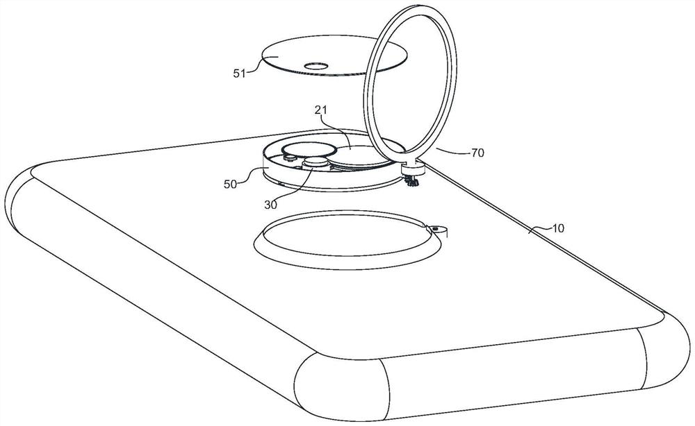
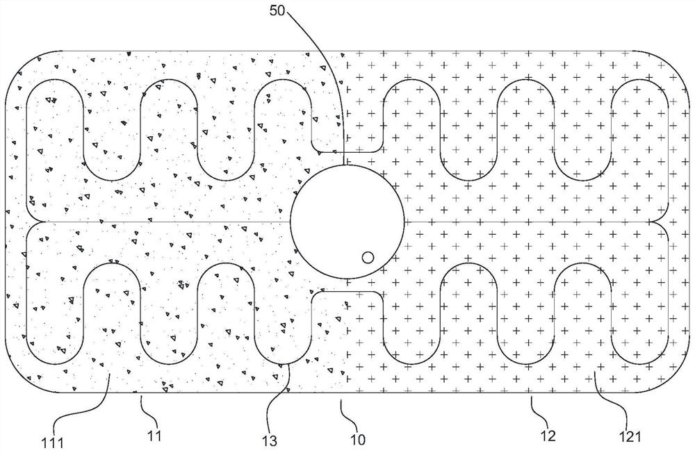
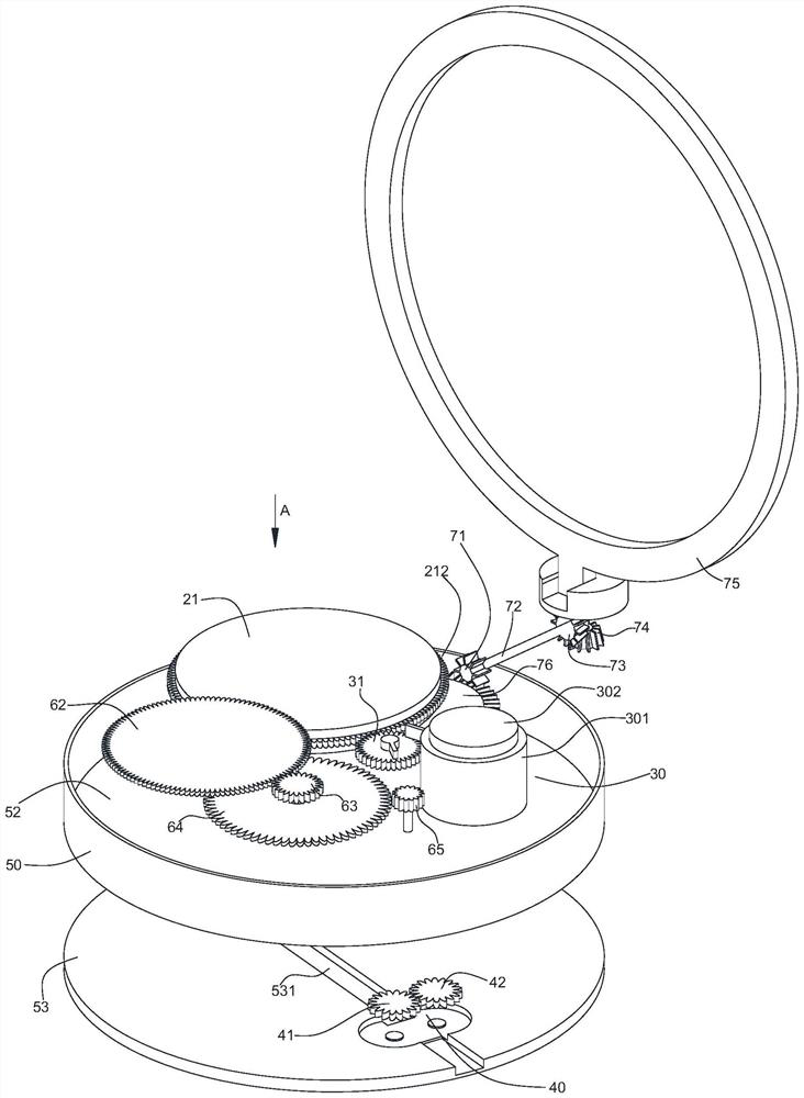
The invention discloses a heat dissipation shell of electronic equipment and the electronic equipment. The heat dissipation shell of the electronic equipment comprises a shell body, a spring box, a pump, a driving assembly and a switch assembly. The shell comprises a first area and a second area, a first phase change material filler is distributed in the first area, and a second phase change material filler is distributed in the second area; a fluid channel in which a heat-conducting medium is arranged is arranged in the shell, and the fluid channel penetrates through the first area and the second area; the power output end of the spring box is connected to the pump, and the liquid inlet end and the liquid outlet end of the pump communicate with the two ends of the fluid channel correspondingly. The driving assembly is connected to the power input end of the spring box and comprises a holding part; the switch assembly is used for controlling the power output end of the spring box to rotate or stop rotating. According to the invention, the surface of the heat dissipation shell has a better uniform temperature characteristic, the heat dissipation capability of the electronic equipment in a high-power-consumption scene is improved, and the electronic equipment is small in size and convenient to carry.

Description

technical field [0001] The invention relates to the field of electronic technology, in particular to a heat dissipation case of an electronic device and the electronic device. Background technique [0002] With the continuous development of electronic technology, the high integration of smart terminals such as mobile phones and tablet computers has become an inevitable trend. The heat dissipation of terminals puts forward higher requirements. Therefore, improving the heat dissipation performance of smart terminals has always been the focus of the industry. [0003] At present, most terminal devices such as mobile phones and tablets use heat pipes, ink copper foil and other internal heat dissipation materials for efficient temperature uniformity. Since the surface adopts natural convection heat dissipation, the overall heat dissipation capacity is limited. With the increase of power consumption The surface temperature of the equipment continues to rise, which affects the use...

Claims


Application Information

Patent Timeline
Patent Type & Authority Applications(China)
IPC IPC(8): H05K7/20H05K5/02
Inventor 陶建云
Owner SHANGHAI WINGTECH INFORMATION TECH CO LTD
Why Eureka
Try Eureka