Liquid crystal display screen stress detection equipment based on clamping type limiting

A technology of liquid crystal display and testing equipment, which is applied in the direction of applying stable tension/pressure to test the strength of materials, testing of machine/structural components, measuring devices, etc. , affecting the accuracy of the pressure test of the LCD screen, etc., to achieve the effect of improving stability and accuracy and ensuring accuracy

Active Publication Date: 2022-01-28
深圳市共赢晶显技术有限公司
View PDF7 Cites 3 Cited by
  • Summary
  • Abstract
  • Description
  • Claims
  • Application Information

AI Technical Summary

Problems solved by technology

[0003] After the current liquid crystal display is produced, it needs to pass the pressure testing equipment to test the pressure of the liquid crystal display to determine whether it is qualified. The current pressure testing equipment is composed of a cylinder and a limiter. The cylinder is used as a pressure drive and a limiter. Limit the side position of the liquid crystal display to ensure that the liquid crystal display has good accuracy when performing pressure detection. Among them, the current limiter in the pressure detection equipment is only squeezed by two opposite baffles on the liquid crystal display Due to the current liquid crystal display is easy to install on the wall, the back of the liquid crystal display is in a gradually raised arc structure. When the liquid crystal display is placed on the workbench, the arc-shaped back and the worktable Fitting, it will cause tilt and offset after placement, and there will be problems when the limiter clamps and limits the LCD screen. When the pressure test is performed under the tilted condition, the force formed by the cylinder on the LCD screen will disperse the components. And it affects the accuracy of the pressure test of the LCD screen; secondly, if a fixed contact plate is used, it cannot be in contact with the curved surface of the LCD screen of different sizes.

Method used


Image

  • Liquid crystal display screen stress detection equipment based on clamping type limiting
  • Liquid crystal display screen stress detection equipment based on clamping type limiting
  • Liquid crystal display screen stress detection equipment based on clamping type limiting

Examples


Embodiment 1

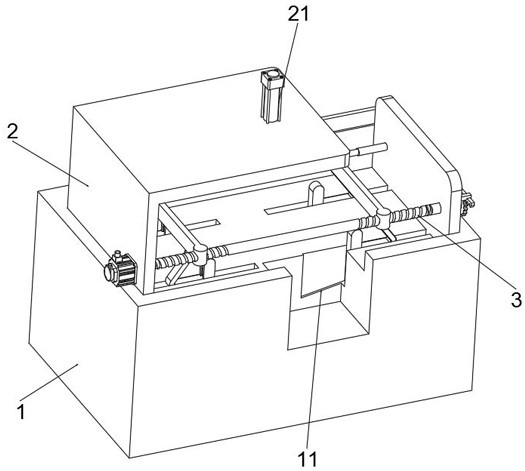
[0044] see Figure 1-Figure 6 As shown, the purpose of this embodiment is to provide a liquid crystal display pressure detection device based on clamping limit, at least including:

[0045] A workbench 1, baffles 2 are symmetrically installed on the surface of the workbench 1, one of the baffles 2 is provided with a horizontal plate on the surface, the surface of the horizontal plate is connected with a cylinder 21, and the cylinder 21 is used to squeeze the liquid crystal display;

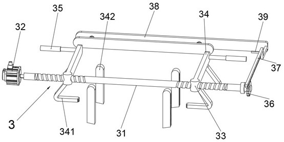
[0046] Limiter 3, limiter 3 is positioned between two baffle plates 2, limiter 3 at least comprises the screw mandrel 31 that is rotatably connected on two baffle plates 2, and the screw groove on the screw mandrel 31 is relatively opened, and the screw One side of the rod 31 runs through the baffle plate 2, and one end of the screw rod 31 is connected with a motor 32, and the motor 32 is fixedly installed with one of the baffle plates 2, and the surface of the screw rod 31 is threadedly connected...

Embodiment 2

[0054] Considering that during the pressure test of the liquid crystal display, when the personnel misuse, the motor 32 drives the limit plate 34 to continue to clamp, causing accidental breakage of the liquid crystal display, this embodiment makes the following improvements on the basis of embodiment 1 ,Such as Figure 7 and Figure 8 Shown:

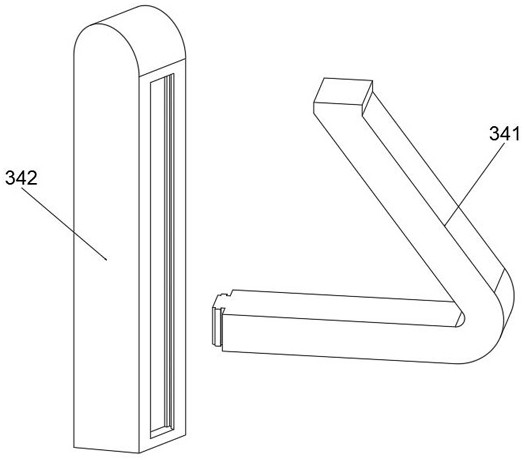
[0055] The surface of the workbench 1 is provided with a chip holder 4, the chip holder 4 at least includes a receiving plate 41, the bottom surface of the receiving plate 41 slides with a left side plate 42, the bottom surface of the left side plate 42 slides with a right side plate 43, and the left side plate 42 and the right side plate 43 alternately slide, and the ends of the left side plate 42 and the right side plate 43 are all equipped with an elastic rope body 44, and the other end of the elastic rope body 44 is fixedly connected with the support rod 342, and the surface of the workbench 1 will remain A large amount of liquid ...

Embodiment 3

[0057] Considering that when a large amount of liquid crystal display pressure is carried out at one time, the liquid crystal display that has passed the test cannot be stored alone, and it is easy to mix with other liquid crystal display screens to affect the work efficiency. This embodiment makes the following on the basis of embodiment 2 improvements such as Figure 9 and Figure 11 Shown:

[0058]A cavity 5 is provided on the side of the workbench 1, a chute 14 is provided on the inside of the cavity 5, a slide plate 51 is provided inside the cavity 5, and a connecting block 511 is installed on the bottom of the slide plate 51, and the connecting block 511 is located in the chute 14 Sliding, by vertically placing the liquid crystal display screen that has passed the pressure test between the slide plate 51 and the cavity 5, through the connection between the connecting block 511 and the chute 14, the slide plate 51 slides to limit the position of the liquid crystal displa...


PUM


Abstract

The invention relates to the technical field of liquid crystal display screens, and in particular relates to liquid crystal display screen pressure detection equipment based on clamping type limiting. The equipment comprises a workbench, baffles are symmetrically installed on the surface of the workbench, a transverse plate is arranged on the surface of one baffle, and an air cylinder is connected to the surface of the transverse plate; a limiting piece at least comprises a lead screw rotationally connected to the two baffles, one side of the lead screw penetrates through the baffles, one end of the lead screw is connected with a motor, the surface of the lead screw is in threaded connection with a lead screw nut, a limiting plate is installed on one side of the lead screw nut, a push rod is installed on the bottom face of the limiting plate, one side of the push rod is movably connected with a supporting rod, a concave cavity is formed in the surface of the workbench, and the supporting rod slides in the concave cavity. The limiting plate approaches and extrudes the liquid crystal display screen, the supporting rod slides down along the concave cavity, the supporting rod is attached to the liquid crystal display screen all the time, the side face of the liquid crystal display screen is limited through the limiting plate, inclination and deviation are avoided, meanwhile, the liquid crystal display screen is kept horizontal, and pressure testing is facilitated.

Description

technical field [0001] The invention relates to the technical field of liquid crystal display screens, in particular to a pressure detection device for liquid crystal display screens based on clip-type position-limiting. Background technique [0002] Liquid crystal display is a kind of flat-panel display, which is used for the screen display of televisions and computers. The advantages of the display are low power consumption, small size and low radiation. [0003] After the current liquid crystal display is produced, it needs to pass the pressure testing equipment to test the pressure of the liquid crystal display to determine whether it is qualified. The current pressure testing equipment is composed of a cylinder and a limiter. The cylinder is used as a pressure drive and a limiter. Limit the side position of the liquid crystal display to ensure that the liquid crystal display has good accuracy when performing pressure detection. Among them, the current limiter in the pr...

Claims


Application Information

Patent Timeline
IPC IPC(8): G02F1/13G01M11/08G01N3/12G01N3/02G01N3/04
CPCG02F1/1309G01M11/08G01N3/12G01N3/02G01N3/04G01N2203/0044G01N2203/0019
Inventor 熊小霞
Owner 深圳市共赢晶显技术有限公司
Why Eureka
Try Eureka