Control method of flyback power supply and control circuit of flyback power supply

A control method and flyback technology, applied in control/regulation systems, high-efficiency power electronic conversion, electrical components, etc., can solve the problems of bad electromagnetic interference, increase the effective value of primary current, and high operating frequency, and achieve increased transmission. Effects of Power Range

Active Publication Date: 2022-01-28
SOUTHCHIP SEMICON TECH SHANGHAI CO LTD
View PDF7 Cites 4 Cited by
  • Summary
  • Abstract
  • Description
  • Claims
  • Application Information

AI Technical Summary

Problems solved by technology

[0006] Problem 1: Increased ripple, obvious audio noise, and worse electromagnetic interference (EMI) caused by frequent switching at the bottom of the valley;
[0007] Question 2: For flyback converters with a wide input range (90Vrms to 264Vrms), when the 90Vac low-voltage input, the bus voltage after rectification usually fluctuates greatly, especially when the high-voltage Bulk capacitance is small, the bus voltage fluctuation peak The peak value will reach 50V or even higher. Because it is difficult to introduce the frequency reduction strategy, under such a wide range of bus voltage fluctuations, there will be multiple valleys when the converter is working at full load, thereby increasing the effective value of the primary current and reducing work efficiency
This solution is a better solution for valley-bottom switching, but the operating frequency is completely determined by the inductance of the power stage and the valley-bottom cycle. When the bus voltage is different, the operating frequency when working in the first valley-bottom state is very different. Work in the first valley state, the operating frequency is higher, and the switching loss is larger

Method used


Image

  • Control method of flyback power supply and control circuit of flyback power supply
  • Control method of flyback power supply and control circuit of flyback power supply
  • Control method of flyback power supply and control circuit of flyback power supply

Examples


Embodiment Construction

[0039] The present invention will be described in detail below in conjunction with the accompanying drawings.

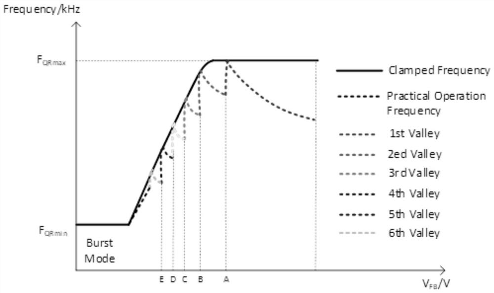
[0040] The operating frequency of the conventional frequency clamping method is as figure 2 As shown, when the QR flyback converter works at the valley switching point, such as point A-E in the figure, frequent valley switching will occur; the reason is: when the converter works near point A, as the load increases slowly, the conversion The converter transitions from the second valley working state to the first valley working state. When working in the first valley working state on the right side of point A, the converter’s transmission power increases due to the increase in operating frequency, and the VFB voltage is adjusted through a negative feedback loop. Decrease, so that the converter returns to the second valley working state on the left side of point A. In this way, the converter will repeatedly switch between the first valley and the second valley.

[00...


PUM


Abstract

The invention belongs to the technical field of switching power supplies, and particularly relates to a control method of a flyback power supply and a control circuit of the flyback power supply. A flyback circuit valley bottom switching problem is solved based on a double-frequency clamping strategy, and a main mode of the double-frequency clamping strategy is that: zero-cross detection is carried out on ZCD signals of a flyback power supply according to periods to obtain valley bottom signals, the valley bottom times of each period are obtained by counting the triggering times of the valley bottom signals, a valley bottom change signal is obtained according to the current valley bottom frequency and the last period valley bottom frequency, and then according to the valley bottom signal, the valley bottom change signal is combined with two groups of signals of a high-frequency clamping signal and a low-frequency clamping signal generated by the frequency control circuit to finally generate a driving signal of a control switch. The change of the opening number of the valley bottoms is limited through the double-frequency clamping, the transmission power range in the same valley bottom state is enlarged, and the situation that the valley bottoms are repeatedly switched due to the change of system input conditions when the valley bottoms are switched near working points is avoided.

Description

technical field [0001] The invention belongs to the technical field of switching power supplies, and in particular relates to a control method and a control circuit of a flyback power supply. Background technique [0002] Flyback converter is also called single-ended flyback or "Buck-Boost" converter. It gets its name because the output terminal gets energy when the primary winding is disconnected from the power supply. The flyback converter is widely used in low-power power supplies and various power adapters because of its simple circuit structure and low cost. [0003] The flyback converter controlled by peak current mode is turned on at the first resonance valley in DCM mode, which is called quasi-resonant (Quasi-Resonant, QR) flyback. In this working state, the turn-on voltage of the switching device is compared with the continuous mode Lower, which is beneficial to reduce switching loss, and the peak current is smaller than that of discontinuous mode, which is benefi...

Claims


Application Information

Patent Timeline
Patent Type & Authority Applications(China)
IPC IPC(8): H02M3/335H02M1/08H02M1/44
CPCH02M3/33523H02M1/08H02M1/44Y02B70/10
Inventor 王楠高建龙
Owner SOUTHCHIP SEMICON TECH SHANGHAI CO LTD
Why Eureka
Try Eureka