
A dynamic current supply circuit and method for reducing ripple

A dynamic current, supply circuit technology, applied in improving amplifiers to reduce temperature/power supply voltage variations, electrical components, amplifiers with semiconductor devices/discharge tubes, etc. To achieve the effect of reducing ripple, reducing load DC current ripple, reducing load DC current ripple and DC voltage ripple

Active Publication Date: 2022-05-20
SHAANXI REACTOR MICROELECTRONICS
View PDF8 Cites 0 Cited by
  • Summary
  • Abstract
  • Description
  • Claims
  • Application Information

AI Technical Summary

Problems solved by technology

[0002] In the prior art, the output of the step-down conversion power supply (buck power supply) has a large output capacitor for filtering the output voltage ripple; since the output of the dynamic current supply circuit has no output capacitor to GND, in order to reduce the DC Current ripple, reduce the inductor current ripple by increasing the inductance value, thereby reducing the DC current ripple, but this will increase the system volume and slow down the response speed when the load is switched

Method used


Image

  • A dynamic current supply circuit and method for reducing ripple
  • A dynamic current supply circuit and method for reducing ripple
  • A dynamic current supply circuit and method for reducing ripple

Examples


Embodiment Construction

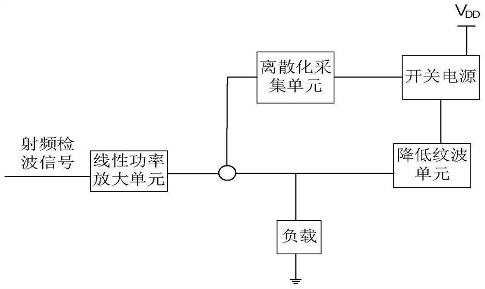
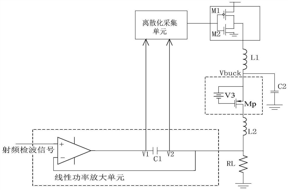
[0036] In order to make the purpose, technical solutions and advantages of the embodiments of the present invention more clear, the following will combine the appended Figure 1 to Figure 6 , clearly and completely describe the technical solutions in the embodiments of the present invention, obviously, the described embodiments are part of the embodiments of the present invention, but not all of them. Based on the implementation manners in the present invention, all other implementation manners obtained by persons of ordinary skill in the art without creative efforts fall within the protection scope of the present invention.

[0037] Accordingly, the following detailed description of the embodiments of the invention provided in the accompanying drawings is not intended to limit the scope of the claimed invention, but merely represents selected embodiments of the invention. Based on the implementation manners in the present invention, all other implementation manners obtained b...


PUM


Abstract

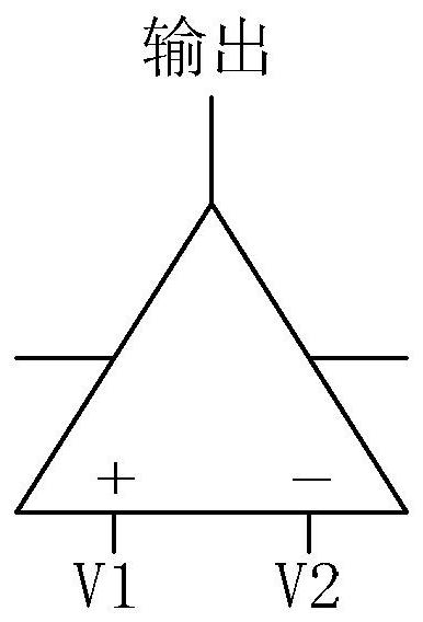
The invention discloses a dynamic current supply circuit and method for reducing ripple, wherein the linear power amplification unit includes a non-inverting input terminal, a reverse input terminal and an output terminal; the discrete acquisition unit includes a positive terminal, a negative terminal and a sampling output terminal The positive end is connected to one end of the capacitor C1 close to the output end of the linear power amplifying unit, and the negative end is connected to the other end of the capacitor C1 far away from the output end of the linear power amplifying unit. The gate and the first drain, the second power MOS transistor includes a grounded second source, a second gate connected to the sampling output terminal, and a second drain connected to the first drain, and the constant current source includes a power transistor and a voltage source , the voltage source and the source of the power tube are connected to the inductor L1, the voltage source is connected to the gate of the power tube Mp, one end of the inductor L2 is connected to the drain of Mp, and the other end is connected to the other end of the capacitor C1 away from the linear power amplifier unit.

Description

technical field [0001] The invention relates to the technical field of dynamic current supply circuits, in particular to a dynamic current supply circuit and method for reducing ripple. Background technique [0002] In the prior art, the output of the step-down conversion power supply (buck power supply) has a large output capacitance for filtering the output voltage ripple; since the output of the dynamic current supply circuit has no output capacitance to GND, in order to reduce the DC Current ripple, reduce the inductor current ripple by increasing the inductance value, thereby reducing the DC current ripple, but this will increase the system volume and slow down the response speed when the load is switched. Therefore, in the case of a fixed inductance value, how to reduce the DC current ripple with little or even no impact on other performances has become an urgent problem to be solved by those skilled in the art. [0003] The above information disclosed in this Backgro...

Claims


Application Information

Patent Timeline
Patent Type & Authority Patents(China)
IPC IPC(8): H03F1/30H03F1/32H03F3/195H03F3/213
CPCH03F1/30H03F1/32H03F3/195H03F3/213H03F2200/451
Inventor 何世宝王佳维夏勤
Owner SHAANXI REACTOR MICROELECTRONICS
Learn More