Catering service robot with visual system

A service robot and vision system technology, applied in the field of catering service robots, can solve the problems of contact collision, large flow of people, easy spillage of food, etc., and achieve the effect of avoiding spillage

Inactive Publication Date: 2022-02-01
宿州恒辉智慧信息科技有限公司
View PDF1 Cites 0 Cited by
  • Summary
  • Abstract
  • Description
  • Claims
  • Application Information

AI Technical Summary

Problems solved by technology

The catering service robot in the above patent has the following disadvantages: Although it can meet certain food delivery needs, due to the large flow of people in restaurants and hotels, it is inevitable that the catering service robot will come into contact with guests when delivering food. The phenomenon of collision, the food inside is very easy to spill, so that it affects the user experience

Method used


Image

  • Catering service robot with visual system
  • Catering service robot with visual system
  • Catering service robot with visual system

Examples


Embodiment 1

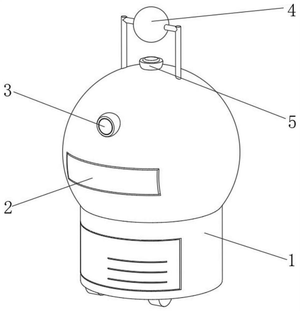
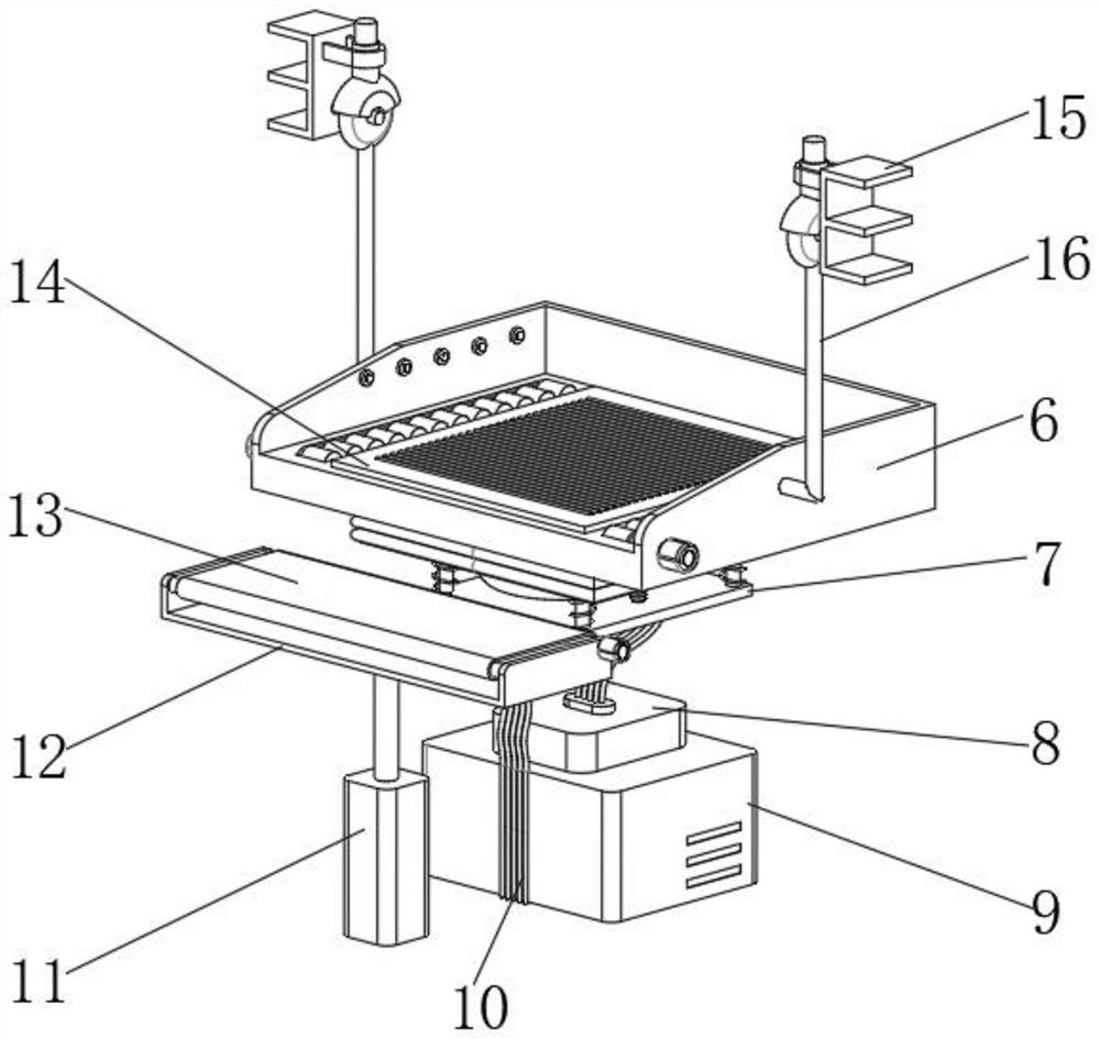
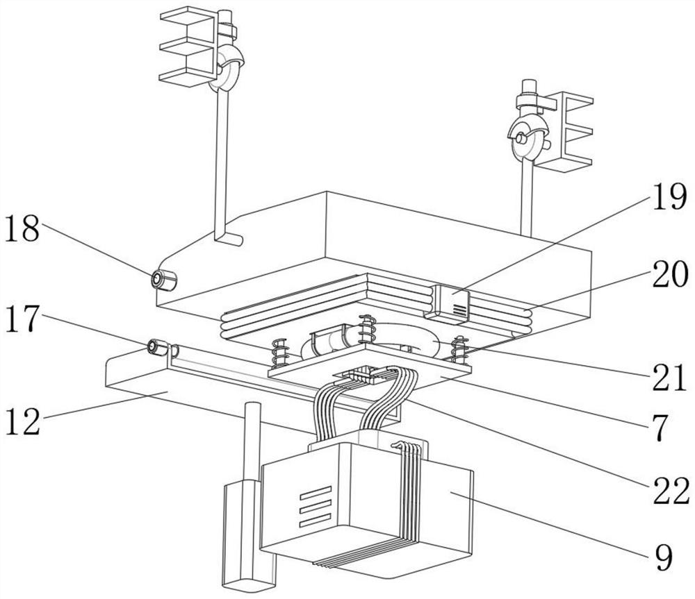
[0048] A food service robot with a vision system such as Figure 1-8 As shown, it includes a main body 1, an electric control door 2 is arranged on one side of the main body 1, and a meal delivery mechanism is arranged inside the main body 1, and the meal delivery mechanism includes a supporting bracket 6 and two connecting rods 16. The connecting rod 16 is fixed on the outer walls on both sides of the support bracket 6 by screws, and the inner walls on both sides of the main body 1 are fixed with two symmetrical fixing frames 15 by screws. The top of the connecting rod 16 is integrally provided with two rotating discs 36, two One end of the rotating disk 36 is rotatably installed on one side inner wall of the two fixed mounts 15 respectively through the shaft, and the outer wall of the top of the rotating disk 36 is provided with a mounting hole, and a fixing pin 38 is installed in the mounting hole by a first spring 37, so that The fixed pin 38 is made of magnetic metal, and...

Embodiment 2

[0060] A food service robot with a vision system such as Figure 9-13 As shown, in order to facilitate the manual opening of the door to take meals, the present embodiment makes the following changes on the basis of Embodiment 1: the electric control door 2 is replaced by a manual door 61, and the two sides of the manual door 61 can be moved through the installation shaft 49. Rotation is installed on the inner wall on both sides of the main body 1, the first synchronous wheel 48 is fixed at the two ends of the installation shaft 49, the outer wall of the first synchronous wheel 48 is connected with the second synchronous wheel 46 through the synchronous belt 47 transmission, the second synchronous wheel 46 can be Rotatingly installed on the inner wall of the main body 1, the outer wall on one side of the second synchronous wheel 46 is fixed with a first gear 59 by screws, the outer wall of the first gear 59 is meshed with the second gear 45, and the outer wall on one side of th...


PUM


Abstract

The invention discloses a catering service robot with a visual system, and relates to the technical field of catering service robots. In order to avoid food spilling during food delivery, the robot specifically comprises a main body, an electric control door is arranged on one side of the main body, a meal delivery mechanism is arranged in the main body, the meal delivery mechanism comprises a bearing frame and two connecting rods, the connecting rods are fixed to the outer walls of the two sides of the bearing frame through screws, and two symmetrical fixing frames are fixed to the inner walls of the two sides of the main body by screws. By arranging the bearing frame, the rotating disc and other structures, when the robot is impacted and collided, the bearing frame can keep food stable and avoid food spilling in the mode that the rotating disc rotates in the fixing frame through a shaft, when food needs to be taken out, the control room controls the first electromagnet to work, a magnetic field is generated to attract a fixing pin. And under the deformation of the first spring, the fixing pin is sucked into the pin hole, so that the rotating disc is fixed, and then the first conveying mechanism conveys the meal to complete food delivery.

Description

technical field [0001] The invention relates to the technical field of catering service robots, in particular to a catering service robot with a vision system. Background technique [0002] With the advancement of science and technology, people's lives are becoming more and more intelligent. Catering service robots are a manifestation of smart catering services. Catering service robots are often set up in restaurants and hotels to provide food delivery and other functions. The current catering service Although robots can meet a certain demand for food delivery, due to the large flow of people in restaurants and hotels, it is inevitable that catering service robots will collide with guests when delivering food, and the food inside is extremely difficult. It is easy to spill, so that it affects the experience of use. [0003] After retrieval, the Chinese patent application number is CN201820350723.8, which discloses a catering service robot, including a robot body, a robot si...

Claims


Application Information

Patent Timeline
Patent Type & Authority Applications(China)
IPC IPC(8): B25J11/00
CPCB25J11/008
Inventor 高波
Owner 宿州恒辉智慧信息科技有限公司
Why Eureka
Try Eureka