Anti-freezing concrete pole with high collision resistance

A technology of concrete and concrete layer, applied in the direction of building type, electrical components, cable installation, etc., can solve the problems affecting the impact strength of concrete poles, cumbersome construction process, poor frost resistance, etc., to achieve all-round performance enhancement, Easy to disassemble and assemble, improve the effect of anti-collision performance

Active Publication Date: 2022-02-01
浙江双新预构件有限公司
View PDF2 Cites 0 Cited by
  • Summary
  • Abstract
  • Description
  • Claims
  • Application Information

AI Technical Summary

Problems solved by technology

[0003] However, the current traditional concrete poles have poor frost resistance. After a period of use, the concrete poles are easily affected by the thermal expansion and contraction of the outside air temperature, resulting in many cracks, which affect the impact strength of the concrete poles, and have a single function. When it is necessary to connect buried cables, additional cable fixing brackets need to be installed, which makes the construction process more cumbersome

Method used


Image

  • Anti-freezing concrete pole with high collision resistance
  • Anti-freezing concrete pole with high collision resistance
  • Anti-freezing concrete pole with high collision resistance

Examples


Embodiment 1

[0036] Please refer to Figure 1 to Figure 9 :

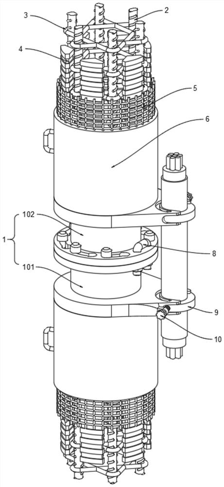
[0037]The present invention proposes a high anti-collision frost-resistant concrete pole, comprising: a connecting piece 1, a steel bar frame 3, a foam strip 4 and a concrete layer 6; Type, and the upper connecting piece 101 is connected to the top of the main steel bar 2, and the lower connecting piece 102 is connected to the bottom end of the main reinforcing bar 2, and the top side of one of the upper connecting pieces 101 is connected to the bottom side of the other lower connecting piece 102; the top of the upper connecting piece 101 There are seven clamping connecting columns 1011 in a circular shape, and seven clamping connecting holes 1021 are provided in a circular shape at the bottom of the lower connecting piece 102. The clamping connecting columns 1011 slide and insert into the clamping connecting holes 1021, and the clamping connecting columns 1011 are connected to the clamping connecting holes 1021. The top side o...

Embodiment 2

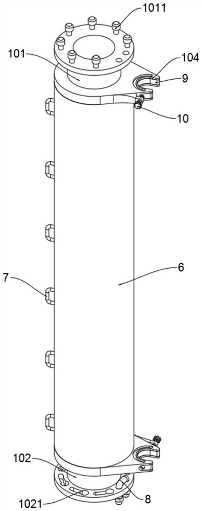
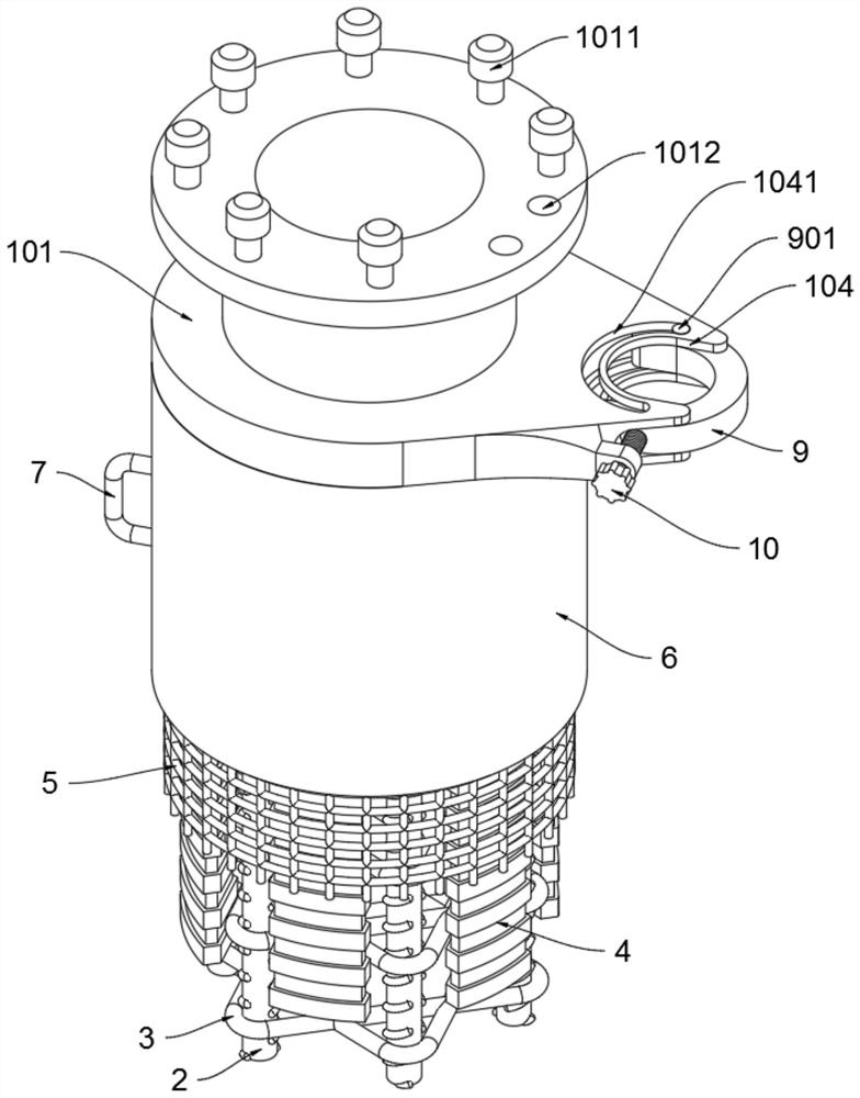
[0045] Cable slots 104 are opened at the same position on the outer side of the upper connecting piece 101 and the outer side of the lower connecting piece 102. The upper and lower sides of the cable slot 104 are respectively provided with arc-shaped slide holes 1041. The U-shaped cable lock 9 is rotatably connected to the cable slot 104. Inside, the upper and lower sides of the U-shaped cable lock 9 are respectively provided with sliders 901, and the sliders 901 are slidably connected in the arc-shaped slide hole 1041, and the outer sides of the upper connecting piece 101 and the outer sides of the lower connecting piece 102 are provided with screw holes 105. The bolt 10 is threadedly connected in the screw hole 105, the outer side of the U-shaped cable lock 9 is provided with a limiting groove 902, and the inner end of the manual bolt 10 is inserted into the limiting groove 902;

[0046] Using the above technical scheme, when it is necessary to connect buried cables, the buri...


PUM


Abstract

The invention provides a high-collision-resistance anti-freezing concrete pole, and relates to the technical field of power supply and transmission. The anti-freezing concrete pole comprises connecting pieces, wherein the connecting pieces are divided into upper connecting pieces and lower connecting pieces, the upper connecting pieces are connected to the top ends of main steel bars, the lower connecting pieces are connected to the bottom ends of the main steel bars, and the top side of one upper connecting piece is connected with the bottom side of the other lower connecting piece; a steel bar frame connected to the outer sides of the main steel bars; and foam strips, wherein the number of the foam strips is six, and the upper ends and the lower ends of the foam strips are connected with the upper connecting pieces and the lower connecting pieces correspondingly. The self weight of the concrete pole is reduced through the foam strips, meanwhile, the concrete pole is subjected to anti-freezing and heat preservation, the thermal expansion and cold contraction coefficient of the concrete pole is reduced, and the concrete pole is prevented from cracking. The problems that a traditional concrete electric pole is poor in anti-freezing performance, after being used for a period of time, the concrete electric pole is prone to being affected by heat expansion and cold contraction of the outside air temperature, many cracks are generated, and the anti-collision strength of the concrete electric pole is affected are solved.

Description

technical field [0001] The invention relates to the technical field of power supply and transmission, in particular to a high-collision-resistant and frost-resistant concrete pole. Background technique [0002] Power poles are bridges for electricity, allowing electricity to be transported to various places. Common poles include wooden poles and cement poles. They are of different heights, stand in the plains and mountains, and spread around people. There are many types of poles, such as: concrete poles, that is, poles made of concrete. [0003] However, the current traditional concrete poles have poor frost resistance. After a period of use, the concrete poles are easily affected by the thermal expansion and contraction of the outside air temperature, resulting in many cracks, which affect the impact strength of the concrete poles, and have a single function. When it is necessary to connect buried cables, a cable fixing frame needs to be installed separately, and the const...

Claims


Application Information

Patent Timeline
Patent Type & Authority Applications(China)
IPC IPC(8): E04H12/12E04B1/78E04G21/32H02G3/32H02G9/06
CPCE04H12/12E04B1/78E04G21/3276H02G3/32H02G9/06Y02A30/30
Inventor 徐斌方方张炎辉倪俊
Owner 浙江双新预构件有限公司
Why Eureka
Try Eureka