Seabed multi-head continuous sampling drilling machine
A sampling drilling rig, multi-head technology, applied in the directions of rotary drilling rigs, drill pipes, drill pipes, etc., can solve the problems of low sampling efficiency, and achieve the effects of easy transportation, compact structure and improved operation efficiency.
- Summary
- Abstract
- Description
- Claims
- Application Information
AI Technical Summary
Problems solved by technology
Method used
Image
Examples
Example Embodiment
[0058] Example one
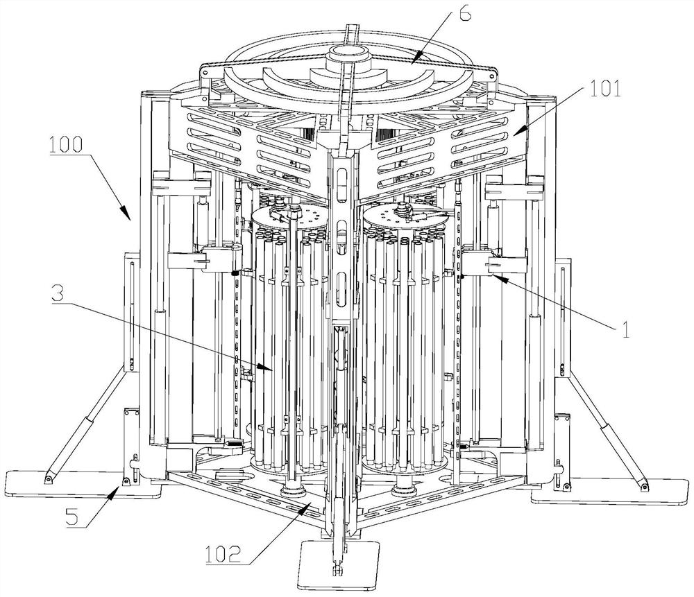
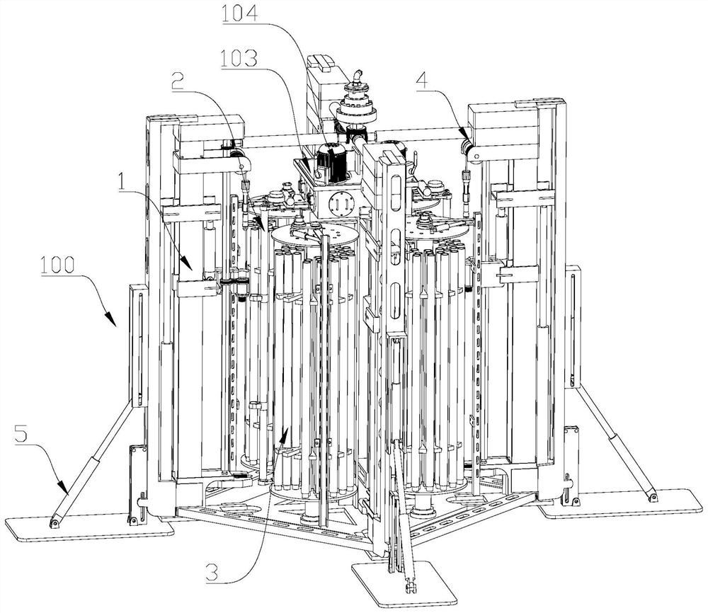
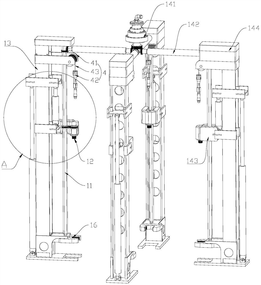
[0059] like Figure 1 - Figure 8 As shown, the present embodiment utilizes a rope to take a heart method, providing a submarine multi-head continuous sampling rig, including a drilling machine 100, a drilling mechanism 1, a drill transfer mechanism 2, and a drill storage mechanism 3, wherein : The power drilling mechanism 1 includes two or more, which includes a vertical shaft 11 and a power head 12 for connecting to the drill pipe 200, and the power head 12 is used to connect to the drill pipe 200, wherein the vertical axis 11 is vertical, and The vertical axis rotatable is rotatably rotatable, and the vertical axis 11 and the power head 12 are driven to drive the power head 12 to rotate, and the power head 12 can move up and down; the drill storage mechanism 3 is used to store drill rods and core tubes, drill The shipping mechanism 2 is used to capture the core tube 300 and the drill pipe 200 and migrate the core tube 300 and the drill rod 200 in the drill st...
Example Embodiment
[0081] Example 2
[0082] This embodiment is an improvement on the basis of the above embodiment, see figure 2 and Figure 5 As shown, the drill 31 of the present embodiment includes a central shaft 311, a turntable 312, and a fixed disk 313, wherein: the central shaft 311 is vertically disposed on the base 102 of the drilling rig 100, and there is two turntable 312 to rotate to the central axis, respectively. On the upper and lower ends of 311, the turntable 312 can rotate in the axis of the central axis 311; see Figure 5 As shown, the drill rod, the bottom end of the core tube is supported on the lower end of the turntable 312. The fixing disc 313 is horizontally arranged between the two turntable 312, and a card slot for the cartridge and / or the core tube is provided on the fixed disk 313.
[0083] See Figure 5 As shown, two drills 31 are provided on both sides of a power drill mechanism 1, one of which can be used to store drill rod 200, and another drill library 31 can be us...
Example Embodiment
[0095] Example three
[0096] This embodiment is an improvement performed on the basis of the above embodiment, and provides a specific embodiment of a drill transfer mechanism 2, see Figure 5 As shown, the drill mounting mechanism 2 includes a rotating cylinder 21, a gripper drive rod 22, and a mechanical gripper 23, wherein: the starting speed of the brake lever 22 is vertically arranged, the drive end of the rotating cylinder 21 passes horizontally connectors and the starting The upper end of the rod 22 is fixed, and the mechanical grip 23 is provided with one or more of the gripper drive rods 22; the rotating cylinder 21 can be swung between the drill storage mechanism 3 and the power head 12 in the drill storage mechanism 3. And the grip can swing to the position of the same vertical line to connect the drill rod and power head 12.
[0097] See Figure 5, The rotational cylinder 21 is rotated, gripper drive transmission rod 22 is rotated, thereby achieving the mechanical movem...
PUM
 Abstract
Description
Claims
Application Information
 - R&D
- Intellectual Property
- Life Sciences
- Materials
- Tech Scout
- Unparalleled Data Quality
- Higher Quality Content
- 60% Fewer Hallucinations
Browse by: Latest US Patents, China's latest patents, Technical Efficacy Thesaurus, Application Domain, Technology Topic, Popular Technical Reports.
© 2025 PatSnap. All rights reserved.Legal|Privacy policy|Modern Slavery Act Transparency Statement|Sitemap|About US| Contact US: help@patsnap.com


