Connecting structure of hydraulic oil cylinder top cover and oil cylinder

A technology of hydraulic oil cylinder and connection structure, applied in the field of hydraulic oil cylinder, can solve the problems of reducing the service life of the top cover, damage to bolts and threaded connection parts, and difficulty in disassembling the top cover of the oil cylinder, and achieves the effect of increasing accumulation and blockage.

Pending Publication Date: 2022-02-01
丁安琦
View PDF0 Cites 0 Cited by
  • Summary
  • Abstract
  • Description
  • Claims
  • Application Information

AI Technical Summary

Problems solved by technology

[0005] The technical problem to be solved by the present invention is: a connection structure between the top cover of the hydraulic cylinder and the oil cylinder provided by the present invention can solve the problem of the connection between the bolt and the screw thread after the oil cylinder and the top cover are affected by factors such as hydraulic pressure and thermal expansion. Damage will cause the connection to be difficult to disassemble or damage the thread and joint surface after disassembly, reducing the service life of the top cover; and it can avoid the problem that the cylinder top cover is not easy to disassemble and hastily disassembled when the pressure in the hydraulic cylinder is too high when the hydraulic cylinder is disassembled The hydraulic cylinder top cover and bolts will be pushed out by pressure and cause personal injury

Method used


Image

  • Connecting structure of hydraulic oil cylinder top cover and oil cylinder
  • Connecting structure of hydraulic oil cylinder top cover and oil cylinder
  • Connecting structure of hydraulic oil cylinder top cover and oil cylinder

Examples


Embodiment approach

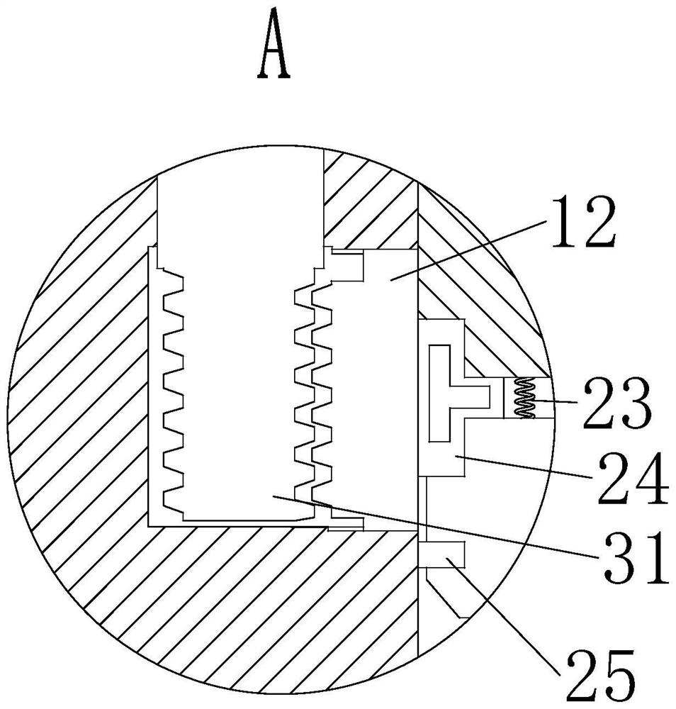
[0025] As a specific embodiment of the present invention, the inside of the No. 1 sealing ring 24 is set as a hollow structure.

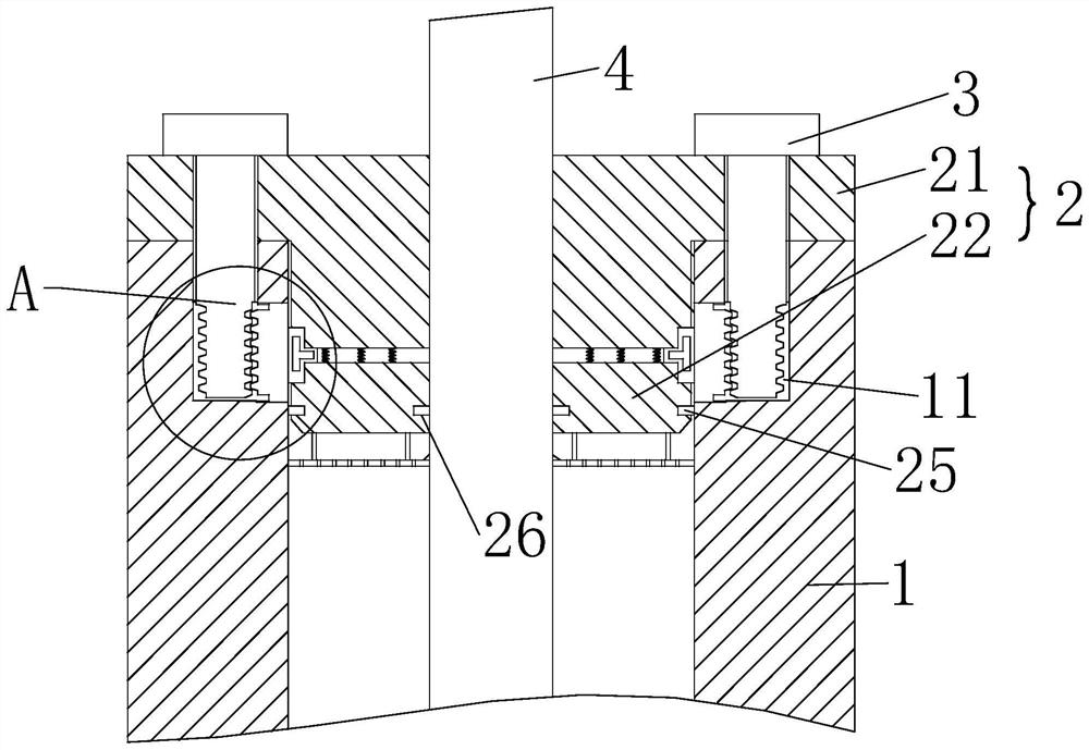
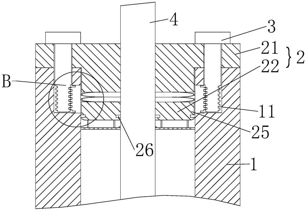
[0026] When the lower top cover 22 in the cylinder body 1 is impacted by factors such as hydraulic pressure and thermal expansion, the No. 1 sealing ring 24 is squeezed by the lower top cover 22 and the upper top cover 21, so that the No. 1 sealing ring 24 is extruded and deformed. The inside of the seal ring 24 is set as a hollow structure, which can make the deformation of the No. 1 seal ring 24 larger and better push the trapezoidal tooth block 12 in the groove 11 to match the trapezoidal tooth bolt 31 on the bolt 3, and the No. 1 seal When the ring 24 is squeezed, the degree of deformation is greater to achieve a better sealing effect;

[0027] As a specific embodiment of the present invention, there are multiple springs 23 arranged evenly, and the springs 23 cooperate with the lower top cover 22 to achieve a buffering effect.

[0028] When the...


PUM


Abstract

The invention relates to the technical field of hydraulic oil cylinders, in particular to a connecting structure of a hydraulic oil cylinder top cover and an oil cylinder. The connecting structure comprises a cylinder body, a top cover, a bolt and a piston rod, wherein the cylinder body is fixedly connected with the top cover through the bolt; a groove is formed in the inner wall of the cylinder body, a first tooth-shaped block is arranged in the groove, the top cover comprises an upper top cover and a lower top cover, a spring is fixedly connected between the upper top cover and the lower top cover, a second tooth-shaped block matched with the first tooth-shaped block is arranged at the bottom end of the bolt, and a first sealing ring is arranged between the upper top cover and the lower top cover; and the sealing ring is extruded and deformed, and the deformed sealing ring pushes the first tooth-shaped block in the groove to be matched with the second tooth-shaped block on the bolt so as to further fix the cylinder body and the top cover, and then the purposes of sharing the pressure borne by the connecting part of the bolt and the thread and preventing the connecting part of the bolt and the thread from being damaged due to the fact that hydraulic pressure and thermal expansion in the cylinder body exert too large force on the top cover, and consequently the connecting part of the bolt and the thread is not easy to disassemble or the thread and the surface of the joint are damaged after disassembly are achieved.

Description

technical field [0001] The invention relates to the technical field of hydraulic oil cylinders, in particular to a connection structure between a hydraulic oil cylinder top cover and an oil cylinder. Background technique [0002] A hydraulic cylinder is a hydraulic actuator that converts hydraulic energy into mechanical energy and performs linear reciprocating motion (or swing motion). It has simple structure and reliable operation. When it is used to achieve reciprocating motion, the deceleration device can be eliminated, and there is no transmission gap, and the movement is stable, so it is widely used in various mechanical hydraulic systems; the output force of the hydraulic cylinder is proportional to the effective area of ​​the piston and the pressure difference on both sides. Proportional; The hydraulic cylinder is basically composed of cylinder barrel and cylinder head, piston and piston rod, and sealing device. [0003] In the prior art, threaded holes and bolts ar...

Claims


Application Information

Patent Timeline
IPC IPC(8): F15B15/14F15B21/041
CPCF15B15/1423F15B15/1438F15B15/1442F15B21/041
Inventor 丁安琦张贤博
Owner 丁安琦
Why Eureka
Try Eureka