Garbage waste treatment system

A technology for waste disposal and treatment system, applied in combustion methods, lighting and heating equipment, combustion types, etc., can solve the problems of carbon deposits that cannot be quickly discharged, affect the workshop environment, affect the work process, etc., to avoid the overflow of incineration waste gas, avoid The effect of exhaust gas overflow and quick positioning and installation

Pending Publication Date: 2022-02-01
HENAN LUTAI ROAD MAINTENANCE MACHINERY
View PDF15 Cites 0 Cited by
  • Summary
  • Abstract
  • Description
  • Claims
  • Application Information

AI Technical Summary

Problems solved by technology

If process-based mechanized treatment needs to integrate the entire equipment, the space is limited, and the feeding location needs to be changed frequently according to needs, and some current feeding equipment is relatively heavy, which is not conducive to changing the feeding location; and for the incinerator There will be a large amount of waste gas overflowing from the feeding port. At present, there is no good solution to prevent a large amount of waste gas from overflowing; the waste gas overflow will affect the workshop environment; and it will be allowed to burn freely after feeding, resulting in insufficient combustion and poor combustion effect. Overheating of the walls, resulting in an excessively high temperature in the workshop
After combustion, the carbon deposits cannot be discharged quickly, which affects production; the smoke exhaust channel causes dust accumulation, resulting in poor ventilation effect for a long time
Moreover, the incinerated garbage will produce a large amount of waste gas, which needs to be treated. Due to the high temperature of the waste gas, it is necessary to cool the waste gas before processing it. At present, most of the cooling and dust removal equipment have a single function, and the cooling effect is poor. Realize rapid cooling, and the dust generated can easily cause the intake pipe or cooling equipment to block and affect the follow-up work process, resulting in low work efficiency

Method used


Image

  • Garbage waste treatment system
  • Garbage waste treatment system
  • Garbage waste treatment system

Examples


Embodiment 1

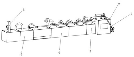
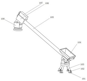
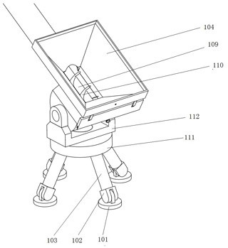
[0063] Such as Figure 1-27 As shown, the purpose of the present invention is achieved in this way: the garbage and waste treatment system includes sequentially connected: a feeding mechanism 1 for transporting garbage and waste; an incinerator mechanism 2 that transports the feeding mechanism into the incinerator mechanism The garbage and waste materials are incinerated; the exhaust gas cooling box 3 sucks the exhaust gas burned by the incinerator mechanism and quickly cools it down; the spray atomization reaction mechanism 4 performs spray atomization reaction on the gas after cooling down from the exhaust gas cooling box, Remove the harmful gas in the exhaust gas and absorb the dust in the exhaust gas, and return part of the gas after the spray atomization reaction to the incinerator, and the other part of the gas flows to the oil fume separation mechanism; the oil fume separation mechanism 5, spray and atomize Part of the exhaust gas after the reaction is subjected to oil fu...


PUM


Abstract

The invention particularly relates to a garbage waste treatment system which comprises a feeding mechanism and an incinerator mechanism which are connected in sequence, wherein garbage waste conveyed into the incinerator mechanism by the feeding mechanism is incinerated; a waste gas cooling box which is used for sucking waste gas generated after incineration of the incinerator mechanism and rapidly cooling the waste gas; a spraying atomization reaction mechanism which is used for carrying out spraying atomization reaction on the gas cooled by the waste gas cooling box, removing harmful gas in the waste gas, adsorbing and removing dust in the waste gas, and enabling one part of the gas subjected to the spraying atomization reaction to flow back to the incinerator and the other part of the gas to flow to the oil smoke separation mechanism; an oil-smoke separation mechanism which is used for carrying out oil-smoke separation on part of the waste gas after the spraying atomization reaction; and a tail gas treatment mechanism which is used for carrying out high-temperature heating treatment on gas obtained after oil fume separation and combusting a small amount of combustible gas contained in treated waste gas. According to the garbage incinerator, garbage waste can be incinerated, and incinerated waste gas is purified.

Description

technical field [0001] The invention belongs to the technical field of garbage treatment, in particular to a garbage waste treatment system. Background technique [0002] Garbage is solid waste generated in human daily life and production. Due to the large amount of discharge, complex and diverse components, and polluting, resourceful and social nature, it needs harmless, resourceful, reduction and socialized treatment. If not handled properly, it will pollute the environment, affect environmental sanitation, waste resources, destroy production and living safety, and disrupt social harmony. Garbage disposal is to quickly remove garbage, and conduct harmless treatment, and finally make reasonable use of it. The garbage disposal methods widely used today are sanitary landfill, high temperature composting and incineration. The purpose of garbage disposal is harmless, resourceful and reduction. [0003] With the rapid development of urbanization, the annual output of urban do...

Claims


Application Information

Patent Timeline
Patent Type & Authority Applications(China)
IPC IPC(8): F23G5/00F23G5/44F23G7/06F23J15/00F23J15/04F23J15/06
CPCF23G5/00F23G5/44F23G5/444F23G7/06F23J15/003F23J15/04F23J15/06F23J2217/50
Inventor 张良奇张培赵金龙王轩田纪荣李连军毋琼胡群才
Owner HENAN LUTAI ROAD MAINTENANCE MACHINERY
Why Eureka
Try Eureka