Laser transmittance detector

A transmittance and detector technology, applied in the direction of optical instrument testing, instruments, measuring devices, etc., can solve the problems of inconvenient laser fixing and disassembly, time-consuming and labor-intensive, high production costs, so as to improve detection efficiency, reduce production costs, High practical effect

Pending Publication Date: 2022-02-01
英普激光科技(苏州)有限公司
View PDF0 Cites 0 Cited by
  • Summary
  • Abstract
  • Description
  • Claims
  • Application Information

AI Technical Summary

Problems solved by technology

[0006] The purpose of the present invention is to provide a laser transmittance detector to solve the problem that the traditional detection equipment is not convenient for quickly fixing and disassembling the laser, which results in time-consuming, laborious and low efficiency when detecting multiple lasers. And most of them use mechanical transmission mechanism to adjust the distance between the laser and the detection board, the production cost is high, which is not conducive to the problem of widespread production and use

Method used


Image

  • Laser transmittance detector
  • Laser transmittance detector
  • Laser transmittance detector

Examples


Embodiment Construction

[0021] The following will clearly and completely describe the technical solutions in the embodiments of the present invention with reference to the drawings in the embodiments of the present invention.

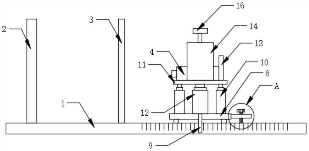
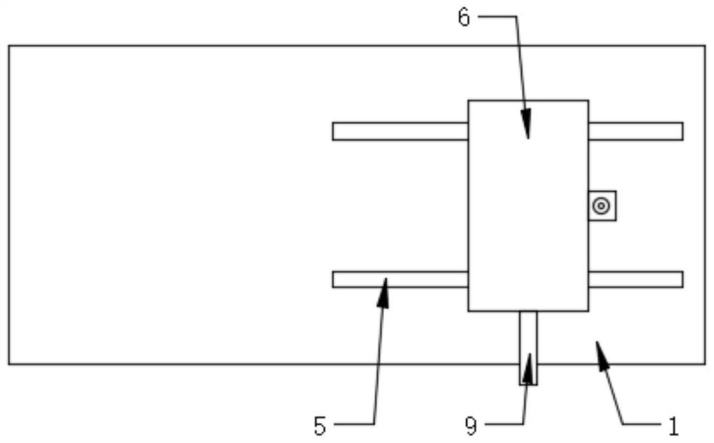
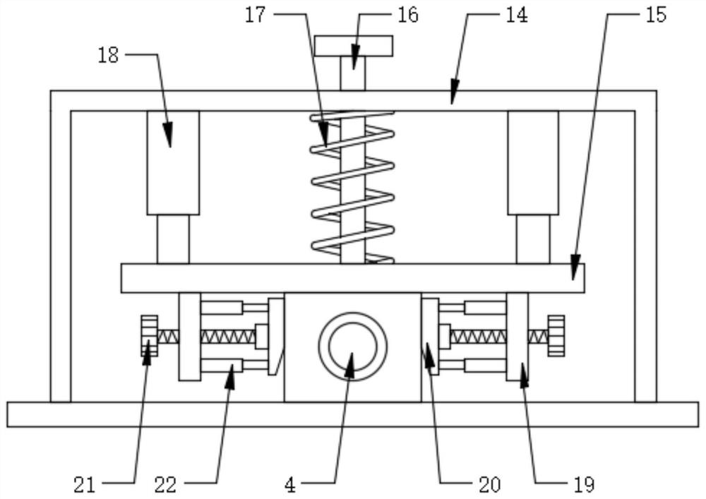
[0022] Such as Figure 1-4 As shown, the present invention provides a technical solution: a laser transmittance detector, including a base 1, a receiving plate 2, a detection plate 3, a moving seat structure, a lifting seat structure, a laser 4, a fast pressing structure and an auxiliary Limiting structure, the upper surface of the base 1 is horizontally provided with two slide grooves 5, the receiving plate 2 and the detection plate 3 are fixedly installed on the upper surface of the base 1, and the moving seat structure is installed on There are two slide grooves 5 on the upper surface of the base 1, the lifting seat structure is installed on the upper surface of the moving seat structure, the laser 4 is movable at the top of the lifting seat structure, and the fast pressing...


PUM


Abstract

The invention discloses a laser transmittance detector which comprises a base, a receiving plate, a detection plate, a moving seat structure, a lifting seat structure, a laser, a rapid pressing structure and an auxiliary limiting structure, two sliding grooves are transversely formed in the surface of the upper end of the base, and the receiving plate and the detection plate are both fixedly installed on the surface of the upper end of the base; and the moving seat structure is installed at the two sliding grooves in the upper surface of the base, the lifting seat structure is installed on the upper end surface of the moving seat structure, the laser is movably located at the top of the lifting seat structure, the rapid pressing structure is installed at the top of the lifting seat structure, the rapid pressing structure abuts against the top of the laser, and the auxiliary limiting structure is mounted at the quick pressing structure. When the laser device is detected, the laser device can be conveniently and rapidly installed, fixed and subsequently disassembled and replaced, time and labor are saved, and the detection work efficiency is greatly improved.

Description

technical field [0001] The invention relates to the field of laser detection equipment, in particular to a laser transmittance detector. Background technique [0002] Laser—A device capable of emitting laser light. In 1954, the first microwave quantum amplifier was made, and a highly coherent microwave beam was obtained. In 1958, A.L. Xiao Luo and C.H. Towns extended the principle of microwave quantum amplifier to the optical frequency range. In 1960, T.H. Maiman and others made it In 1961, A. Jia Wen and others made a helium-neon laser. In 1962, R.N. Hall and others created a gallium arsenide semiconductor laser. After that, there are more and more types of lasers, according to the work In terms of media, lasers can be divided into four categories: gas lasers, solid-state lasers, semiconductor lasers, and dye lasers. After the laser is produced, it needs to be tested for its laser transmittance, which requires the use of testing equipment. [0003] However, existing detec...

Claims


Application Information

Patent Timeline
Patent Type & Authority Applications(China)
IPC IPC(8): G01M11/02G01M11/00
CPCG01M11/02G01M11/00
Inventor 牛庆亚
Owner 英普激光科技(苏州)有限公司
Why Eureka
Try Eureka