Fractured rock hydraulic coupling test device and method for applying constant fracture water pressure

A hydraulic coupling and test device technology, which is applied in the direction of applying stable tension/pressure to test the strength of materials, measuring devices, instruments, etc., can solve the problems that cannot meet the stability of water pressure in cracks, the decrease of water pressure, and the mechanical properties of cracked rock samples and disruptive behavior

Pending Publication Date: 2022-02-01
NANHUA UNIV
View PDF5 Cites 0 Cited by
  • Summary
  • Abstract
  • Description
  • Claims
  • Application Information

AI Technical Summary

Problems solved by technology

However, in the actual test, it was found that after the crack entered the unstable expansion stage, the crack expansion speed was very fast, and a relatively large crack space would be added in a very short period of time, and the constant flow of water could not flow into the newly added crack space in time. Supplementing the same volume of high-pressure water cannot satisfy the stability of the water pressure in the fissure, resulting in a significant decrease in the water pressure in the fissure, and the stable water pressure in the fissure is what causes the tunnel (or roadway, chamber and cavern) to induce water inrush disasters one of the main sources of
In addition, although the auxiliary water injection holes on the fractured rock samples are small in volume, the drilling of the fractured rock samples will still affect the mechanical properties and failure behavior of the fractured rock samples.

Method used


Image

  • Fractured rock hydraulic coupling test device and method for applying constant fracture water pressure
  • Fractured rock hydraulic coupling test device and method for applying constant fracture water pressure
  • Fractured rock hydraulic coupling test device and method for applying constant fracture water pressure

Examples


Embodiment Construction

[0035]The following will clearly and completely describe the technical solutions in the embodiments of the present invention with reference to the accompanying drawings in the embodiments of the present invention. Obviously, the described embodiments are only some, not all, embodiments of the present invention. Based on the embodiments of the present invention, all other embodiments obtained by persons of ordinary skill in the art without making creative efforts belong to the protection scope of the present invention.

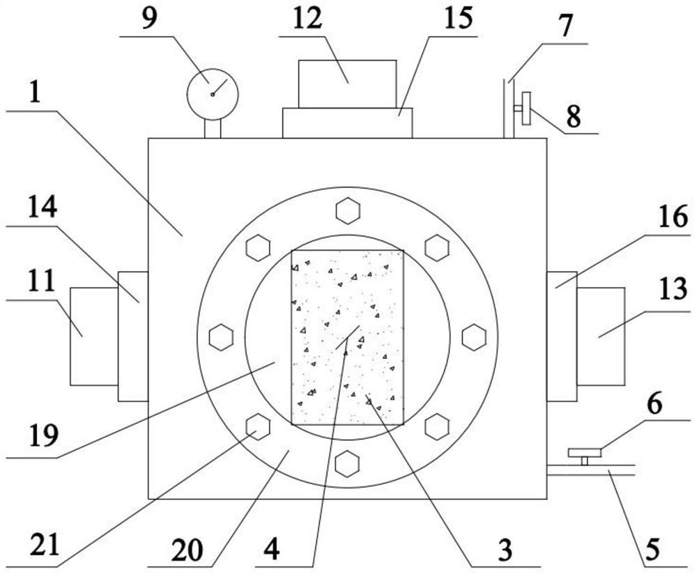
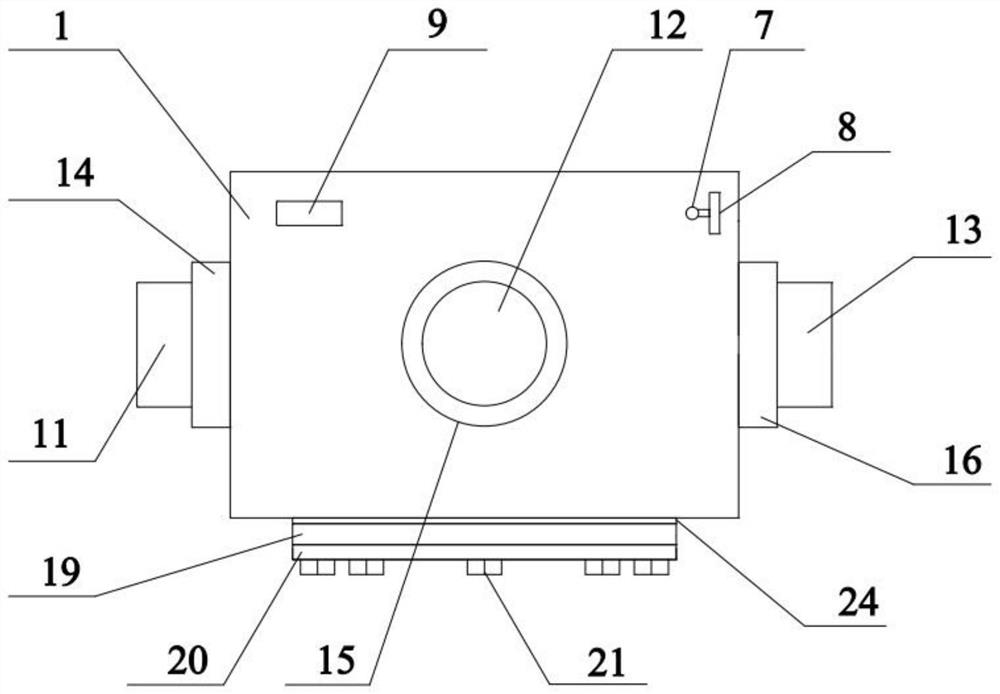
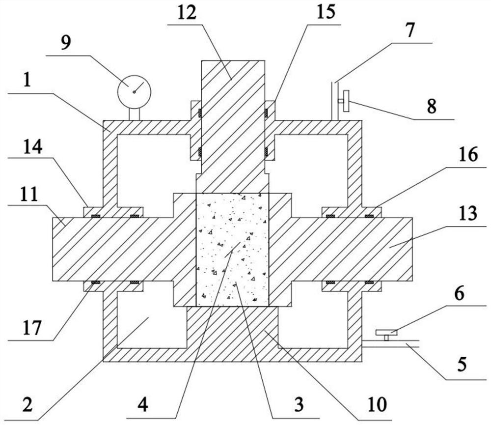
[0036] This embodiment provides a fractured rock hydraulic coupling test device that applies a constant hydraulic pressure in the fracture, such as Figure 1 to Figure 7 As shown, the apparatus body 1 is included, and the interior of the apparatus body 1 is provided with a cavity 2 that can be injected with water. The liquid port 5 is provided with a water inlet and outlet valve 6, and the exhaust port 7 is provided with an exhaust valve 8. The bottom of the c...


PUM


Abstract

The invention discloses a fractured rock hydraulic coupling test device applying constant fracture water pressure, and belongs to the technical field of rock engineering. The test device comprises a device body which is internally provided with a cavity; the device body is provided with a liquid inlet, an exhaust port and a water pressure gauge which are communicated with the cavity; a base is arranged in the cavity, and a single crack is formed in the rock sample; wherein the device body is provided with a force transmission mechanism for pressurizing a rock sample, and the cavity after water injection can ensure that a single fracture is always filled with water, so that constant fracture water pressure is provided. The invention further provides a fractured rock hydraulic coupling test method applying the constant fracture water pressure. The method comprises the steps of: s1, mounting the fractured rock hydraulic coupling test device; s2, mounting a rock sample; s3, applying initial stress; s4, applying fracture water pressure; s5, performing stress loading and fracture extension observation; s6, draining water and taking out the rock sample. According to the invention, the rock sample is horizontally unloaded and vertically loaded, so that the process of reducing the radial stress and increasing the tangential stress of the surrounding rock during excavation is simulated.

Description

technical field [0001] The invention relates to the technical field of rock engineering, in particular to a fracture rock hydraulic coupling test device and method for applying constant fracture water pressure. Background technique [0002] The fractured rock mass is a common complex geological body in the construction process of underground engineering, and the fractured rock mass usually contains fissure water. With the development of underground engineering to deeper underground, the geological environment of fractured rock mass has become more complex, often showing the characteristics of high ground stress and high fracture water pressure. Under the action of natural cracks, the expansion and interpenetration of primary fissures are easy to occur, resulting in the weakening of rock mass strength and the instability and damage of engineering structures. In this environment, mining or tunnel excavation can easily induce serious engineering geological disasters. Especiall...

Claims


Application Information

Patent Timeline
Patent Type & Authority Applications(China)
IPC IPC(8): G01N3/12G01N3/02
CPCG01N3/12G01N3/02
Inventor 罗勇黄建成蒲成志张志军贺桂成
Owner NANHUA UNIV
Why Eureka
Try Eureka