Equivalent yield strength line-shaped optimized diamond-shaped opening anti-buckling type metal energy dissipater being replaceable after earthquake
A yield strength and anti-buckling technology, applied in the field of diamond-shaped opening anti-buckling metal energy dissipators, can solve the problem of difficult control of unfavorable displacement of metal energy dissipation plates, low cross-sectional utilization of metal energy dissipators, and weakened energy dissipation of energy dissipators Capacity and other issues, to avoid the impact of thermal stress, flexible and adjustable bearing capacity and elastic stiffness, and obvious seismic effect
- Summary
- Abstract
- Description
- Claims
- Application Information
AI Technical Summary
Problems solved by technology
Method used
Image
Examples
Embodiment 1
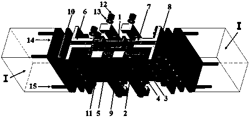
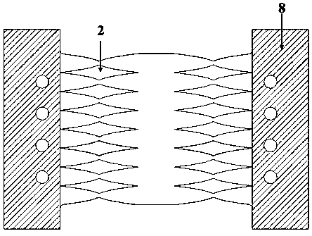
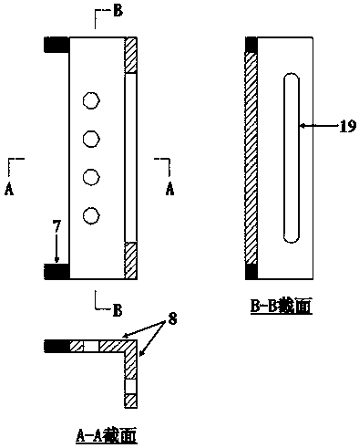
[0028] figure 1It is a schematic diagram of the structure of this embodiment. This embodiment consists of an energy-dissipating metal plate 1, a diamond-shaped opening pass 2 optimized by the shape of the equal yield strength line, an anti-buckling plate 3, a stiffening rib 4 with a limit function, a smooth surface 5, and an L-shaped support 6. Bit key 7, friction surface 8, prestressed lock 9, friction plate 10, high-strength bolt 11, nut 12, washer 13, embedded connecting steel plate 14, anchor piece 15, threaded bolt hole 16, slideway 19 constitute. During assembly, the energy-dissipating metal plate 1 and the L-shaped support 6 are positioned according to the corresponding positions of the bolt holes, and are fixed by high-strength bolts 11 , nuts 12 and washers 13 . Place the anti-buckling plate 3 on the inner and outer sides of the energy-dissipating metal plate 1, and the stiffening rib 4 with the limit function faces outward, and each anti-buckling plate 3 needs to b...
Embodiment 2
[0036] Figure 8 It is a structural sectional view of the present embodiment. A plurality of energy-dissipating metal plates 1 are connected in parallel, and a separator 17 separates two energy-dissipating metal plates 1 . When the energy dissipator is in operation, it not only constrains the out-of-plane deformation of the energy dissipating metal plate 1 but also avoids mutual interference between multiple energy dissipating metal plates 1 , and the rest of the structure is the same as that of the first embodiment.
[0037] Figure 9 It is a schematic diagram of a pair of partitions 17 in this embodiment. Smooth concave surfaces 18 are provided on the inner and outer sides of the middle to reduce friction with the energy-dissipating metal plate 1. Milling machine technology can be used. Corresponding bolt holes are provided at both ends, and friction surfaces 8 are provided at the clamping parts around the holes. Appropriate gaps should be reserved between a pair of parti...
Embodiment 3
[0039] Figure 10 It is a schematic diagram of the structure of this embodiment. Multiple energy dissipators are installed between the upper and lower beams of the frame structure. During earthquake or wind vibration, shear relative displacement occurs between the layers of the frame structure, and the in-plane shear hysteresis mechanism of the energy dissipator is used to dissipate energy. The energy dissipator The upper end is pre-embedded in the concrete part of the upper frame beam II of the frame beam, and the lower end is pre-embedded in the connecting pier III. The strength of the connecting pier should be greater than the shear bearing capacity of the energy dissipator. connected. Energy consumers can be placed in multiple rows and columns according to actual space and design requirements. Other structures are the same as in Embodiment 1.
PUM
 Abstract
Description
Claims
Application Information
 - R&D
- Intellectual Property
- Life Sciences
- Materials
- Tech Scout
- Unparalleled Data Quality
- Higher Quality Content
- 60% Fewer Hallucinations
Browse by: Latest US Patents, China's latest patents, Technical Efficacy Thesaurus, Application Domain, Technology Topic, Popular Technical Reports.
© 2025 PatSnap. All rights reserved.Legal|Privacy policy|Modern Slavery Act Transparency Statement|Sitemap|About US| Contact US: help@patsnap.com


