
Testing method of semiconductor structure

A test method and semiconductor technology, applied in the semiconductor field, can solve problems such as test errors, adverse effects, and misplaced clients, and achieve the effects of reducing display errors, improving test productivity, and reducing retest rates

Pending Publication Date: 2022-02-01
SHANGHAI HUALI MICROELECTRONICS CORP
View PDF11 Cites 0 Cited by
  • Summary
  • Abstract
  • Description
  • Claims
  • Application Information

AI Technical Summary

Problems solved by technology

[0004] In practice, since each wafer needs to test thousands of WAT electrical parameters, it is inevitable that a wafer contains WAT electrical parameters with unqualified test results, and the test accuracy of existing testing machines is difficult to achieve. In the case of 100%, it is difficult to distinguish whether the unqualified test result is the unqualified WAT electrical parameter or the test error in the existing technology, which leads to the high retest rate of WAT test, which seriously affects the production capacity of WAT test (test machine)
On the other hand, the misplacement in the existing WAT process (the first test result shows that it is qualified but the actual failure is regarded as qualified) also has a relatively large adverse impact on subsequent shipments to the client

Method used


Image

  • Testing method of semiconductor structure
  • Testing method of semiconductor structure
  • Testing method of semiconductor structure

Examples


Embodiment Construction

[0022] In order to make the purpose, advantages and features of the present invention clearer, the present invention will be further described in detail below in conjunction with the accompanying drawings and specific embodiments. It should be noted that the drawings are all in very simplified form and not drawn to scale, and are only used to facilitate and clearly assist the purpose of illustrating the embodiments of the present invention. In addition, the structures shown in the drawings are often a part of the actual structure. In particular, each drawing needs to display different emphases, and sometimes uses different scales.

[0023] As used in the present invention, the singular forms "a", "an" and "the" include plural objects, the term "or" is usually used in the sense of including "and / or", and the term "several" Usually, the term "at least one" is used in the meaning of "at least one", and the term "at least two" is usually used in the meaning of "two or more". In a...


PUM


Abstract

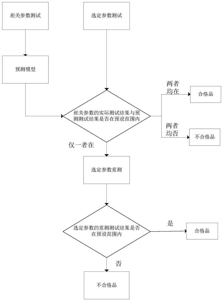
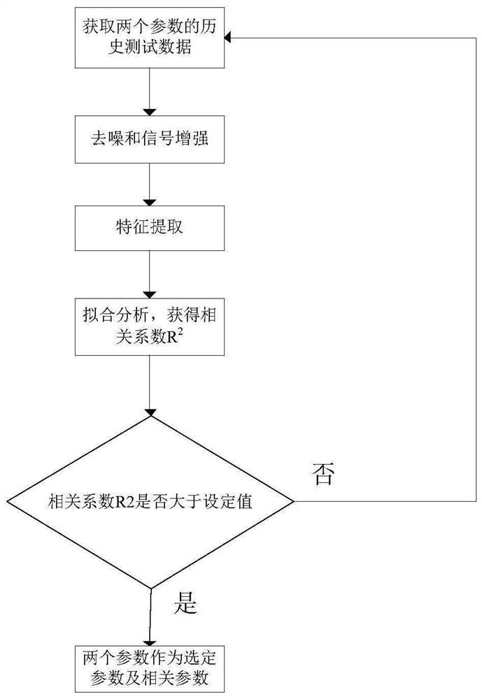
The invention provides a testing method of a semiconductor structure. The method comprises the following steps of: providing an actual test result of a plurality of parameters of the semiconductor structure, wherein the plurality of parameters comprise selected parameters and related parameters; acquiring a prediction test result of the selected parameters based on a prediction model; judging whether the actual test result and a predicted test result of the selected parameters are in a preset range or not; if both the results are within or not within the preset range, determining that the test result of the selected parameters is normal; and if only one of the two results is within the preset range, determining that the test result of the selected parameters is abnormal, and re-testing the selected parameters of the semiconductor structure. According to the testing method, the predicted test result of the selected parameters is compared with the actual test result to diagnose the actual test result, so that the test is accurate, the diagnosis of the test result of the semiconductor structure can be quickly realized, the overall retest rate can be reduced, the condition that the actual test result is consistent but the prediction test result is not consistent can be screened out, and unqualified products are prevented from flowing downstream.

Description

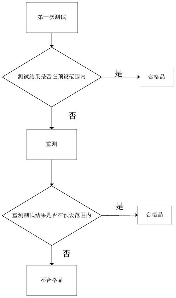
technical field [0001] The invention relates to the field of semiconductor technology, in particular to a method for testing a semiconductor structure. Background technique [0002] WAT (Wafer acceptance test, Wafer Acceptance Test) is an electrical measurement (WAT electrical parameter test) of the wafer after the process is completed and before shipment. It is used to check whether each process process meets the standard. The test items include Device characteristic test, capacitance test, contact resistance test, breakdown test, etc. [0003] In the existing technology, such as figure 1 As shown, after completing the first test of the wafer WAT electrical parameters and obtaining the actual test results, retest and screen the unqualified WAT electrical parameters in the actual test results to reduce the impact of test errors on the wafer yield. Influence, while the WAT electrical parameters shown as qualified in the actual test results are directly regarded as qualified...

Claims


Application Information

Patent Timeline
Patent Type & Authority Applications(China)
IPC IPC(8): G01R31/26H01L21/66
CPCG01R31/2601G01R31/2648H01L22/14
Inventor 陈艺文薛萌陈旭毛贵蕴王勇
Owner SHANGHAI HUALI MICROELECTRONICS CORP
Learn More