Motor performance testing device with torsion adjusting function

A torque adjustment and testing device technology, applied in motor generator testing, measuring devices, measuring device casings, etc., can solve the problems of motor problems that cannot be found in time, invariable torque load, and less data, and avoid inaccurate testing. Avoid high temperature and reduce the effect of friction coefficient

Active Publication Date: 2022-02-01
山东凯欧电机科技有限公司
View PDF7 Cites 4 Cited by
  • Summary
  • Abstract
  • Description
  • Claims
  • Application Information

AI Technical Summary

Problems solved by technology

[0005] In order to overcome the shortcoming that the torque load is not variable, the measured data is less, the problems existing in the motor cannot be found in time, and the unqualified motor leaves the factory, the technical problem of the present invention is to provide a motor performance testing device with torque adjustment function

Method used


Image

  • Motor performance testing device with torsion adjusting function
  • Motor performance testing device with torsion adjusting function
  • Motor performance testing device with torsion adjusting function

Examples


Embodiment 1

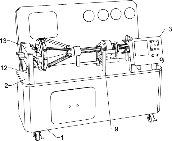
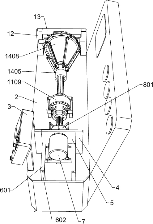
[0030] A motor performance testing device with torque adjustment function, such as Figure 1-Figure 12 As shown, it includes a support frame 1, a support plate 2, a control panel 3, a first fixing bar 4, a first fixing plate 5, a fixing mechanism, a tightening mechanism, a third fixing bar 9, a bearing 10, a protection mechanism, and a fourth fixing Bar 12, groove plate 13 and torsion adjustment mechanism, the upper end of support frame 1 is fixedly connected with support plate 2, and control panel 3 is installed on the right front part of the upper surface of support plate 2, and the front and rear of the upper surface of support plate 2 are fixed respectively. The first fixing bar 4 is connected, and the first fixing plate 5 is fixedly connected between the inner surfaces of the two first fixing bars 4. The middle part of the first fixing plate 5 is provided with a circular rotation groove for fixing the motor 7 to be tested. The fixing mechanism is arranged on the right sid...

Embodiment 2

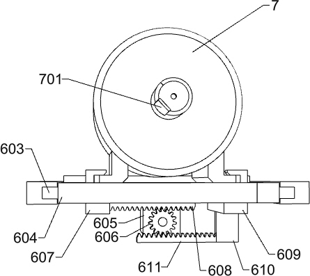
[0033] On the basis of Example 1, such as Figure 2-Figure 4 As shown, the fixing mechanism includes an electric sliding rail 601, a second fixing bar 602, an electric sliding bar 603, a first sliding plate 604, a servo motor 605, a first gear 606, a first clamping frame 607, and a first rack 608. , the second clamping frame 609, the first fixed block 610 and the second rack 611, there are two electric slide rails 601 in total, and the two electric slide rails 601 are respectively affixed to the front and rear parts of the first fixed plate 5 on the right side , the two electric slide rails 601 are electrically connected to the control panel 3 respectively, the right ends of the two electric slide rails 601 are fixedly connected with the second fixing strips 602 respectively, and the two second fixing strips 602 are fixedly connected to the upper right side of the support plate 2 respectively. The two electric slide rails 601 are slidably connected with an electric sliding bar...


PUM


Abstract

The invention relates to the field of motor performance testing, in particular to a motor performance testing device with a torsion adjusting function. The invention solves the technical problems that the torque load cannot be changed, and the measured data is less, so that the problems of the motor cannot be found in time, and the unqualified motor leaves the factory. According to the technical scheme, the motor performance testing device with the torsion adjusting function comprises a supporting plate, a first fixing strip, a first fixing plate, a fixing mechanism and the like; and first fixing strips are fixedly connected to the front and rear portions of the right side of the upper surface of the supporting plate, a first fixing plate is fixedly connected between the inner side faces of the two first fixing strips, and the fixing mechanism is arranged on the right side of the first fixing plate. According to the invention, the fixing mechanism is arranged, so that inaccurate measured data caused by vibration of a to-be-tested motor in the testing process is avoided; and by arranging a torsion adjusting mechanism, inaccurate testing of the to-be-tested motor due to less measured data is avoided.

Description

technical field [0001] The invention relates to the field of motor performance testing, in particular to a motor performance testing device with torque adjustment function. Background technique [0002] Motors can be seen everywhere in daily life. As an indispensable part of the drive device, precise assembly must be done during the production of the motor. Before the motor is assembled and shipped out, an accurate test should be done on the torque, power, and speed of the motor. The technician judges whether the motor is qualified according to the measured data and whether it reaches the factory standard. [0003] When using the existing motor performance test device, the motor is fixed on the test device to test it. Most of the test devices make the motor drive a specific load for testing. Since the torque load is not variable, the measured torque and other data are less. The working state of the test motor cannot be fully reflected in the data, resulting in problems in t...

Claims


Application Information

Patent Timeline
IPC IPC(8): G01R31/34G01R1/04G01R1/02G01L5/00
CPCG01R31/343G01R1/0425G01R1/02G01L5/0042
Inventor 孙明灿赵一泉赵烁宇
Owner 山东凯欧电机科技有限公司
Why Eureka
Try Eureka