
An electrical automation relay protection device

A relay protection and relay technology, applied in the direction of electromagnetic relays, relays, detailed information of electromagnetic relays, etc., can solve the problems of reducing the heat dissipation effect of relays, damage of relays, and easy adhesion of dust on the outer surface of relays, so as to improve heat dissipation effect and reduce energy consumption. Power consumption, easy to dissipate heat

Active Publication Date: 2022-05-17
江门市福宝电器有限公司
View PDF15 Cites 0 Cited by
  • Summary
  • Abstract
  • Description
  • Claims
  • Application Information

AI Technical Summary

Problems solved by technology

[0003] During the working process of the relay, in order to prevent it from being damaged by the external environment, most of the relays are equipped with protection devices to improve the service life of the relay. However, the setting of the protection device reduces the heat dissipation effect of the relay. There is a problem of damage due to high temperature. At the same time, dust is easy to adhere to the outer surface of the relay. The adhered dust will further reduce the heat dissipation effect of the relay and eventually cause damage to the relay.

Method used


Image

  • An electrical automation relay protection device
  • An electrical automation relay protection device
  • An electrical automation relay protection device

Examples


Embodiment Construction

[0030] The following will clearly and completely describe the technical solutions in the embodiments of the present invention with reference to the accompanying drawings in the embodiments of the present invention. Obviously, the described embodiments are only some, not all, embodiments of the present invention. Based on the embodiments of the present invention, all other embodiments obtained by persons of ordinary skill in the art without making creative efforts belong to the protection scope of the present invention.

[0031] In order to make the above objects, features and advantages of the present invention more comprehensible, the present invention will be further described in detail below in conjunction with the accompanying drawings and specific embodiments.

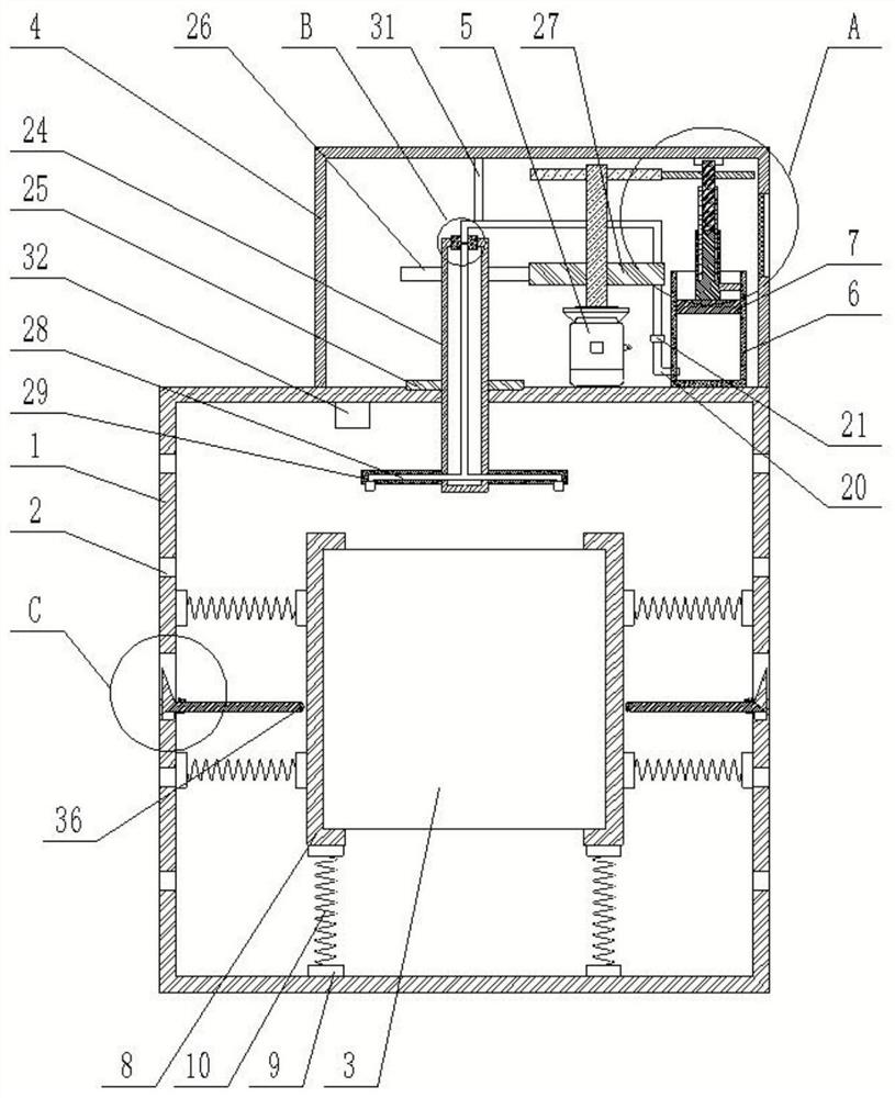
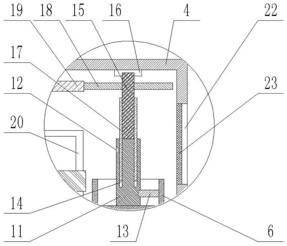
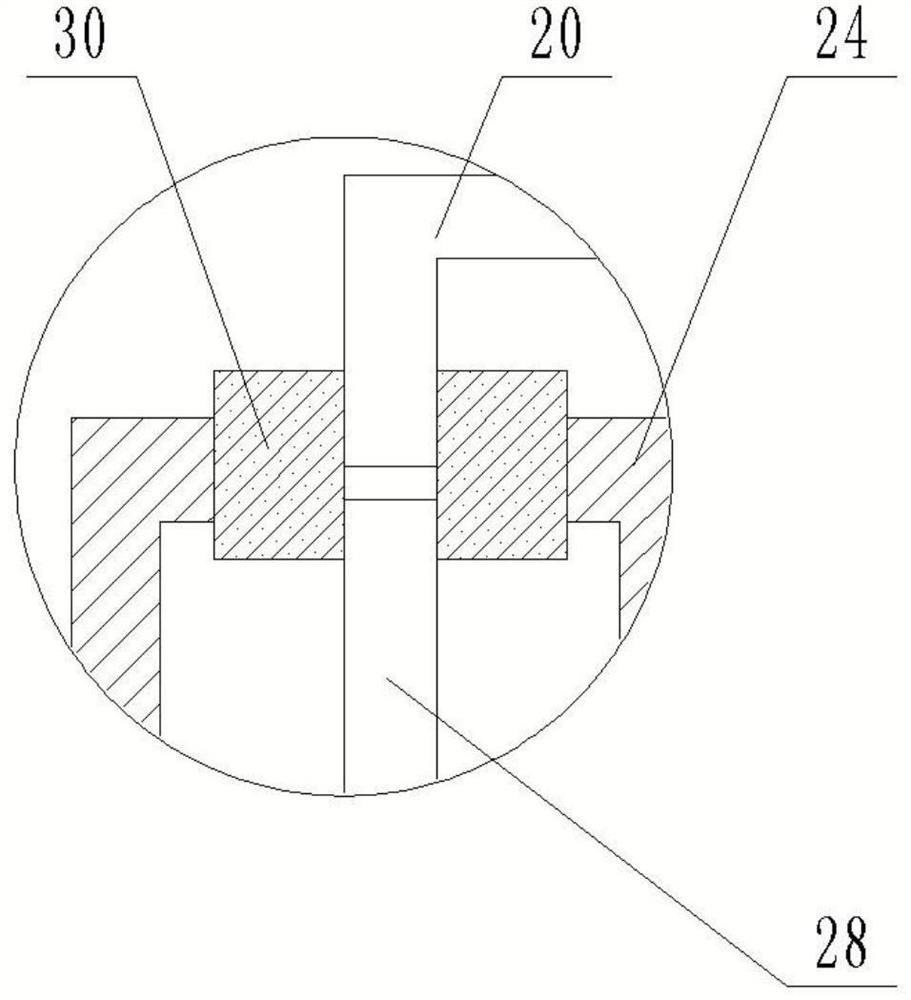
[0032] The invention provides a relay protection device for electrical automation, which includes a protective case 1, a plurality of heat dissipation holes 2 are opened on the side wall of the protective case 1, a...


PUM


Abstract

The invention discloses a relay protection device for electrical automation, which comprises a protective case, a plurality of cooling holes are opened on the side wall of the protective case, a relay and a shock-absorbing part are arranged in the protective case, the relay is connected with the protective case through the shock-absorbing part, and the top of the protective case is fixed. A heat dissipation part is connected, and the heat dissipation part passes through the top of the protective case, and the heat dissipation part is arranged correspondingly to the top of the relay; the heat dissipation part includes a shell fixed to the top of the protective shell, and a driving motor is arranged in the shell, and the driving motor is fixedly connected to the top of the protective shell. The output end of the driving motor is connected with an air supply part and a cooling part, and the cooling part passes through the top of the protective case and is located above the relay, and the cooling part is rotationally connected with the protective case through the driving motor. The invention can achieve heat dissipation and dust removal for the relay on the basis of shock absorption protection for the relay, and only one driving motor is provided. On the one hand, the effect of heat dissipation and dust removal is good, and on the other hand, energy consumption is reduced.

Description

technical field [0001] The invention relates to the technical field of electrical protection, in particular to an electrical automation relay protection device. Background technique [0002] The relay is an electrical control device, which is an electrical appliance that causes the controlled quantity to undergo a predetermined step change in the electrical output circuit when the change of the input quantity meets the specified requirements. It plays the role of automatic adjustment, safety protection, conversion circuit etc. [0003] During the working process of the relay, in order to prevent it from being damaged by the external environment, most of the relays are equipped with protection devices to improve the service life of the relay. However, the setting of the protection device reduces the heat dissipation effect of the relay. There is a problem of damage due to high temperature. At the same time, dust is easy to adhere to the outer surface of the relay. The adhere...

Claims


Application Information

Patent Timeline
Patent Type & Authority Patents(China)
IPC IPC(8): H01H50/04H01H50/12H01H45/04H01H45/12F16F15/04B08B5/02
CPCH01H50/047H01H50/12H01H45/04H01H45/12F16F15/04B08B5/02
Inventor 陶忠良赵文卓王志刚
Owner 江门市福宝电器有限公司
Learn More