
A hook type commutator

A commutator, hook type technology, applied in the direction of current collectors, rotary current collectors, electrical components, etc., can solve the problems of reducing the insulation of the commutator segment, affecting the performance of the motor, and flying out the commutator segment, so as to improve economic benefits. , Improve the service life and ensure the effect of insulation

Active Publication Date: 2022-05-17
浙江科固电器有限公司
View PDF11 Cites 0 Cited by
  • Summary
  • Abstract
  • Description
  • Claims
  • Application Information

AI Technical Summary

Problems solved by technology

[0005] First: The commutator segments of the DC motor are respectively connected to the rotor winding coils. The commutator segments themselves are insulated from each other. When the motor is running, the carbon brushes rub against the commutator segments, which will generate some carbon powder, and some will be deposited on the commutator If there is too much deposition in the groove of the commutator, because the carbon powder conducts electricity, it will reduce the insulation between the commutator segments, or even conduct directly between the commutator segments, which will affect the performance of the motor. In severe cases, it will spark or even form a ring fire , seriously affecting the operation and performance of the motor;
[0006] Second: When the motor rotates, centrifugal force will be generated, causing the commutator to fly out of the inner sleeve, affecting the performance of the motor, and the commutator will fly out, requiring replacement of the commutator and high maintenance costs

Method used


Image

  • A hook type commutator
  • A hook type commutator
  • A hook type commutator

Examples


Embodiment Construction

[0041]The technical solutions of the present invention will be clearly and completely described below in conjunction with the accompanying drawings. Apparently, the described embodiments are some of the embodiments of the present invention, but not all of them.

[0042] The components of the embodiments of the invention generally described and shown in the figures herein may be arranged and designed in a variety of different configurations. Accordingly, the following detailed description of the embodiments of the invention provided in the accompanying drawings is not intended to limit the scope of the claimed invention, but merely represents selected embodiments of the invention.

[0043] Based on the embodiments of the present invention, all other embodiments obtained by persons of ordinary skill in the art without making creative efforts belong to the protection scope of the present invention.

[0044] In the description of the present invention, it should be noted that the ...


PUM


Abstract

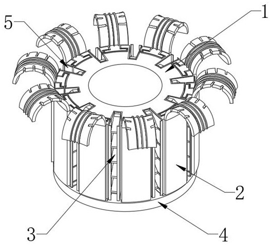
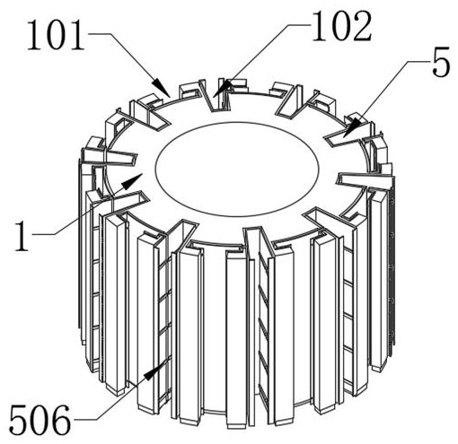
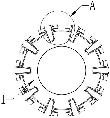
The invention discloses a hook-type commutator, which relates to the technical field of motor accessories, and includes an inner sleeve and a commutator piece. There are multiple commutator pieces, and each side of the commutator piece close to the inner sleeve is fixedly connected with a locking block , a plurality of slots are fixed on the outer peripheral wall of the inner sleeve, a separation slot is fixed between two adjacent slots, a cleaning component is movable in the separation slot, and a through hole is fixed between the separation slot and the slot. The bottom of the inner sleeve is fixedly connected with a fixed ring, the top of the fixed ring is abutted and connected with the bottom of the commutator piece, and a ferrule assembly is embedded and connected between the outer wall of the block and the inner wall of the slot, and the other end of the ferrule assembly is inserted into the separation groove through the through hole Among them, the other end of the ferrule assembly is located between the separation groove and the cleaning assembly. The commutator piece of the present invention is installed stably, can process carbon powder in time, prevents the carbon powder from passing through the commutator piece, and improves the stability of the motor.

Description

technical field [0001] The invention relates to the technical field of motor accessories, in particular to a hook-type commutator. Background technique [0002] The commutator is an important component of the armature of DC motors and AC commutator motors. When the motor rotates, it plays the role of commutation. The commutator is a component used for current commutation on DC motors and AC series motors. In order to allow the motor to continue to rotate, it is commonly known as a commutator. The commutator products mainly include hook-type commutator, slot-type commutator and There are three types of end face commutators. The main part of the hook-type commutator is the hook-type commutator piece with a hook portion. There are multiple independent hook-type commutator pieces distributed along the circumference of the commutator. Each hook-type commutator The segment is combined with the commutator base through its fixing feet. [0003] Chinese Patent Publication No. CN21...

Claims


Application Information

Patent Timeline
Patent Type & Authority Patents(China)
IPC IPC(8): H01R39/04H01R39/46
CPCH01R39/04H01R39/46
Inventor 白直焕白直崇何檬檬
Owner 浙江科固电器有限公司
Learn More