Numerical control precise four-stage rolling mill for ore screen machining

A continuous rolling mill and mining screen technology, applied in metal processing equipment, metal rolling, manufacturing tools, etc., can solve the problems of raw metal wire shaking, affecting rolling quality, raw material wire falling on the ground, etc., to achieve guaranteed The effect of one-way rotation

Pending Publication Date: 2022-02-15
安徽屹翔滤材有限公司
View PDF12 Cites 0 Cited by
  • Summary
  • Abstract
  • Description
  • Claims
  • Application Information

AI Technical Summary

Problems solved by technology

The structures of flat rolling units I, III and vertical rolling units II and IV are exactly the same, and the speeds of each unit are different. They are distributed by pass according to the total elongation coefficient of the rolled piece με=2.5-2.7, and the roll line speed of each unit is adapted to it. But this prior art still has some deficiencies, for example: the raw metal wire is pulled out from the wire reel and enters the inside of the rolling mill, and the wire reel is often subject to a stronger pulling force, especially when the rolling mill is just started, the wire reel is subjected to The force will rotate a lot of times, so that the raw metal wire will be pulled out a large section, so that it is easy to wrap around other structures, bringing safety hazards. At the same time, the raw metal wire will fall on the ground under its own gravity, stained Dust affects the subsequent rolling quality; the wire coil often rotates back and forth, which will cause the raw metal wire to shake back and forth, which is not conducive to the wire feeding operation of the rolling mill

Method used


Image

  • Numerical control precise four-stage rolling mill for ore screen machining
  • Numerical control precise four-stage rolling mill for ore screen machining
  • Numerical control precise four-stage rolling mill for ore screen machining

Examples


Embodiment 1

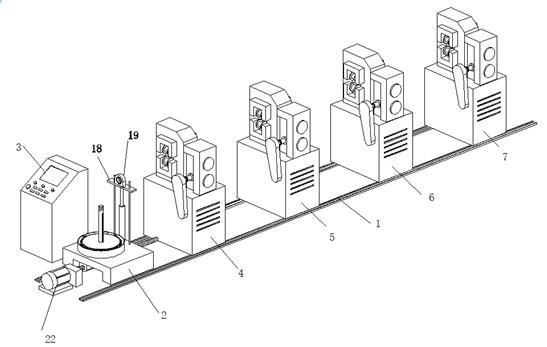
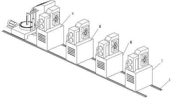
[0033] A kind of numerical control precision continuous rolling mill for mine screen processing, such as Figure 1-Figure 6As shown, it includes rail 1, wire rack 2 and electrical control cabinet 3, and the upper end of rail 1 is installed with wire rack 2, first-stage rolling mill 4, second-stage rolling mill 5, third-stage rolling mill 6 and fourth-stage rolling mill in sequence from left to right 7. Both the first-stage rolling mill 4 and the third-stage rolling mill 6 are horizontal transmission rolling mill units, the second-stage rolling mill 5 and the fourth-stage rolling mill 7 are both vertical transmission rolling mill units, the first-stage rolling mill 4, the second-stage rolling mill 5, the third-stage rolling mill 6 and The structures of the four-stage rolling mill 7 are all the same and are existing equipment, and the rolling mill is mainly composed of a roll, a frame, a roll gap adjustment device, a roll temperature adjustment device, a transmission device, a lu...

Embodiment 2

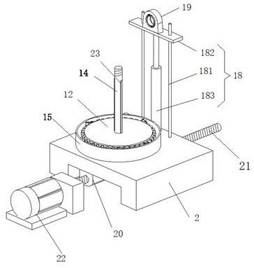
[0039] Embodiment 2 is on the basis of embodiment 1, as figure 1 and image 3 As shown, the height adjustment assembly 18 is also installed on the upper end of the wire drawing frame 2. The height adjustment assembly 18 includes a guide rod 181, a supporting plate 182 and an electric cylinder 183. A pair of guide holes are provided on the surface of the supporting plate 182, and the supporting plate 182 is slidably installed at the same time. On the outer wall of a pair of guide rods 181 , the center position of the bottom end surface of the support plate 182 is fixed to the telescopic end of the electric cylinder 183 , and the electric cylinder 183 is electrically connected with the electric control cabinet 3 .

[0040] Embodiment 2 During the rolling process, the electric cylinder 1 can be controlled by the electric control cabinet 3 to extend or shorten, thereby driving the supporting plate 182 to move upward or downward for a certain distance, and the top of the height adj...

Embodiment 3

[0042] Embodiment 3 is on the basis of embodiment 2, as figure 1 and Figure 8 As shown, the top of the height adjustment assembly 18 is fixed with a guide wire assembly 19, and the guide wire assembly 19 includes a guide wire seat 191, a guide sleeve 192, a cage 193 and a ball 194, and the guide wire seat 191 has a circular ring inside the guide wire seat 191. The hole 195, the inside of the round hole 195 is covered with a guide sleeve 192, and a number of ball mounting holes are formed inside the cage 193. The cage 193 is fixed inside the annular space formed between the round hole 195 and the guide sleeve 192, and inside the cage 193 Several balls 194 are installed in rotation.

[0043] Embodiment 3 During the rolling process, the raw metal wire will pass through the inside of the guide sleeve 192, and the setting of the ball 194 enables the guide sleeve 192 to rotate along the inside of the wire guide seat 19, so that the raw metal wire is more smooth when conducting. T...


PUM


Abstract

The invention relates to the technical field of ore screen machining, in particular to a numerical control precise four-stage rolling mill for ore screen machining, which comprises a track, a wire releasing frame and an electric control cabinet, the wire releasing frame, a first-stage rolling mill, a second-stage rolling mill, a third-stage rolling mill and a fourth-stage rolling mill are sequentially mounted at the upper end of the track from left to right, and a rotating shaft is mounted at the upper end of the wire releasing frame through a bearing seat. A plurality of round rods are fixed to the outer wall of the rotating shaft, overspeed prevention assemblies are installed at the outer ends of the round rods correspondingly, a rotating disc is fixed to the top end of the rotating shaft, a ratchet ring is fixed to the outer wall of the rotating disc, a fixed shaft is fixed to the upper end of the rotating disc, a circular ring block is further fixed to the upper surface of the wire releasing frame, and a plurality of pawls are hinged to the inner wall of the periphery of the circular ring block. The back faces of the pawls abut against leaf springs. The raw material metal wire can stably enter the rolling mill, and normal wire discharging is ensured; and the rotating disc can only rotate in one direction, and the rotation phenomenon is avoided.

Description

technical field [0001] The invention relates to the technical field of mine screen processing, in particular to a numerically controlled precision four-rolling mill for mine screen processing. Background technique [0002] Mine screen is a metal mesh structure element used for sieving and filtering. Applied to screening, filtration, dehydration, desliming and other operations. It has high strength, rigidity and bearing capacity, and can be made into rigid screening and filtering devices of various shapes, which are easy to leak, wear-resistant and corrosion-resistant. The cross-section of the mesh is trapezoidal, and the gap is narrow at the top and wide at the bottom. Among them, the rolling mill is a common equipment in the production and processing of mine screens. The rolling mill deforms the metal material through strong pressure to obtain the required shape of the material. At the same time, the internal residual stress and stress concentration can be eliminated duri...

Claims


Application Information

Patent Timeline
Patent Type & Authority Applications(China)
IPC IPC(8): B21B1/16B21B39/02B21C47/20B21C47/34
CPCB21B1/16B21B39/02B21C47/20B21C47/34
Inventor 丁好奇韩同清李金成王体亚
Owner 安徽屹翔滤材有限公司
Why Eureka
Try Eureka