
Lathe electric spindle limiting structure

A limit structure, electric spindle technology, applied in metal processing equipment, metal processing machinery parts, manufacturing tools, etc., can solve the problems of bolt damage, failure to ensure the stability of electric spindle and equipment, and inability to adapt to various installation environments , to prolong the service life

Active Publication Date: 2022-02-15
江苏星晨高速电机有限公司
View PDF12 Cites 0 Cited by
  • Summary
  • Abstract
  • Description
  • Claims
  • Application Information

AI Technical Summary

Problems solved by technology

[0004] The above patents also have the following problems: 1. The principle of using bolts to deform metal is difficult to achieve the expected fixing effect under low temperature conditions, and the bolts will produce irreversible damage due to large stress during use, making the bolts 2. It is mainly used to install electric spindles, but the equipment has not been improved for the main application scenarios of electric spindles, lacks the structure and related method descriptions installed on other equipment, and cannot be adapted to various installations The environment cannot guarantee the stability of the operation of the motorized spindle and the device itself after the device is used to install the motorized spindle

Method used


Image

  • Lathe electric spindle limiting structure
  • Lathe electric spindle limiting structure
  • Lathe electric spindle limiting structure

Examples


Embodiment

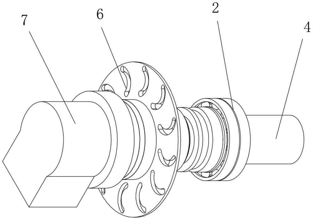
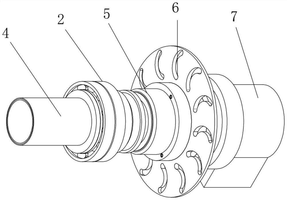
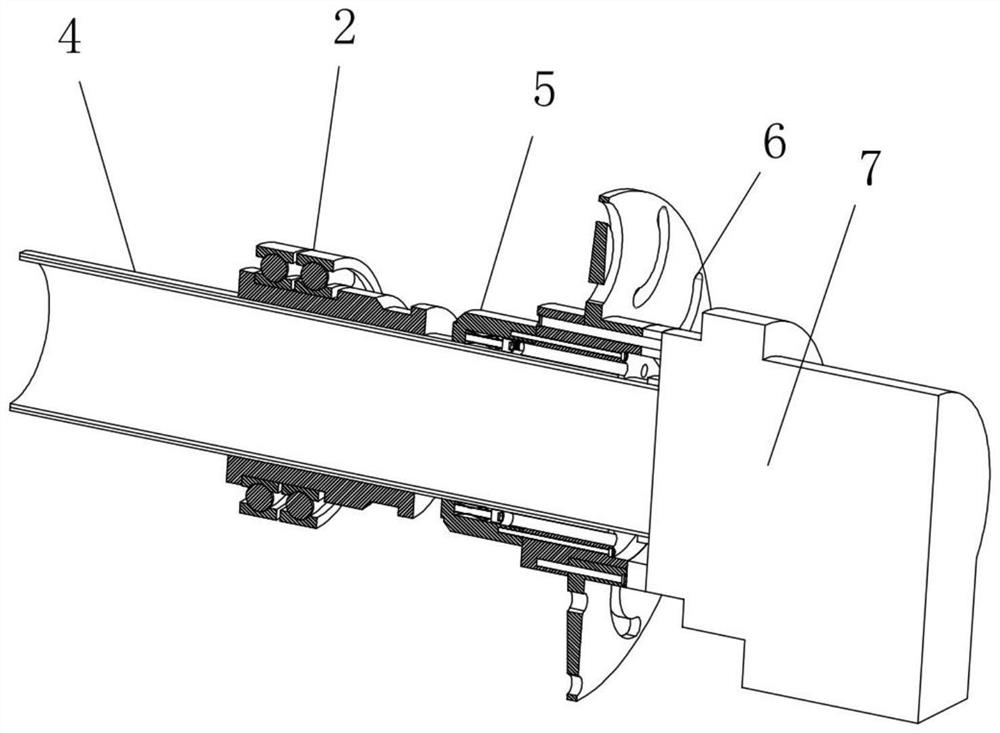
[0035]In the installation work of the A2-6 interface lathe electric spindle 1, a lathe electric spindle limit structure provided by the present invention is used as the limit structure when installing the electric spindle 1. The A2-6 series electric spindle 1 is considering various designs When required, the shaft is affected by various aspects, and the shaft wall is extremely thin, only 8.5mm thick, so the axial limit step cannot be generated; the tail end must also ensure load bearing, and the traditional radial key positioning method cannot be used to reduce the electric current. The rigidity of the main shaft 1; the threaded hole on the side of the shaft is tightened with a standard screw, and the short thread is not enough for the force bearing surface, and also reduces the rigidity of the electric main shaft 1. Therefore, a new solution is urgently needed to solve the above problems, so the present invention is designed as an electric motor. The new method of installing t...


PUM


Abstract

The invention discloses a lathe electric spindle limiting structure, and relates to the technical field of spindle mounting equipment. The lathe electric spindle limiting structure comprises an electric spindle, wherein the outer wall of the electric spindle is sleeved with an auxiliary fixing mechanism and an expansion sleeve base, an interference expansion sleeve is fixedly connected to the interior of the expansion sleeve base and comprises an outer ring, an inner ring concentric with the outer ring is arranged in the outer ring, the inner wall of the inner ring is in contact with the outer wall of the electric spindle, the inner wall of the outer ring and the outer wall of the inner ring are each of a wedge-shaped structure with the middle protruding, the two sides of the outer ring and the two sides of the inner ring are each provided with a pressing ring in a sliding and embedded mode, and the side face of one pressing ring is fixedly connected with an annular gasket. The two pressing rings symmetrically arranged on the inner ring and the outer ring are locked and fixed through using locking bolts, the two locking rings start to move oppositely so as to extrude the inner ring and the outer ring, the outer ring is difficult to expand due to limiting of a fixing sleeve, the inner ring can contract inwards to a certain degree so as to apply pressure to the electric spindle, and therefore the fixing effect on the electric spindle is achieved.

Description

technical field [0001] The invention relates to the technical field of electric spindle installation equipment, in particular to a limit structure for a lathe electric spindle. Background technique [0002] The electric spindle is a new technology that integrates the machine tool spindle and the spindle motor in the field of CNC machine tools. The spindle is a set of components, which includes the electric spindle itself and its accessories: electric spindle, high-frequency frequency conversion device, oil mist lubricator, cooling device, built-in encoder, tool changer, etc. This type of transmission structure in which the spindle motor and the machine tool spindle are "combined into one" makes the spindle components relatively independent from the transmission system and the overall structure of the machine tool, so it can be made into a "spindle unit", commonly known as "electric spindle", with characteristics For high speed, high precision, low noise, the structure with ...

Claims


Application Information

Patent Timeline
IPC IPC(8): B23B19/02
CPCB23Q1/70
Inventor 刘钊黄龙梅
Owner 江苏星晨高速电机有限公司
Learn More