Rack for binding prefabricated box girder top plate reinforcement cage

A steel skeleton and steel bar technology, applied in bridges, bridge materials, bridge construction, etc., can solve the problems of slowing down the construction progress, uneven spacing of steel bars, inaccurate positioning, etc., to improve work efficiency, speed up the progress of construction, The effect of evenly spaced rebars

Pending Publication Date: 2022-02-18
HEBEI CONSTR GRP CO LTD
View PDF0 Cites 0 Cited by
  • Summary
  • Abstract
  • Description
  • Claims
  • Application Information

AI Technical Summary

Problems solved by technology

[0003] Generally, the roof reinforcement skeleton is tied directly above the base of the bridge pier, followed by concrete pouring. However, due to the large span between the bridge piers, it is extremely inconvenient to operate, and during the operation, due to the lack of supporting structures below, And the reasons for high-altitude operations are likely to cause uneven spacing of steel bars, inaccurate positioning, and easier deformation after binding, which greatly slows down the progress of construction

Method used


Image

  • Rack for binding prefabricated box girder top plate reinforcement cage
  • Rack for binding prefabricated box girder top plate reinforcement cage
  • Rack for binding prefabricated box girder top plate reinforcement cage

Examples


Embodiment Construction

[0030] In order to help better understand the technical solutions of the present application, the specific embodiments of the present application will be described in detail below with reference to the accompanying drawings.

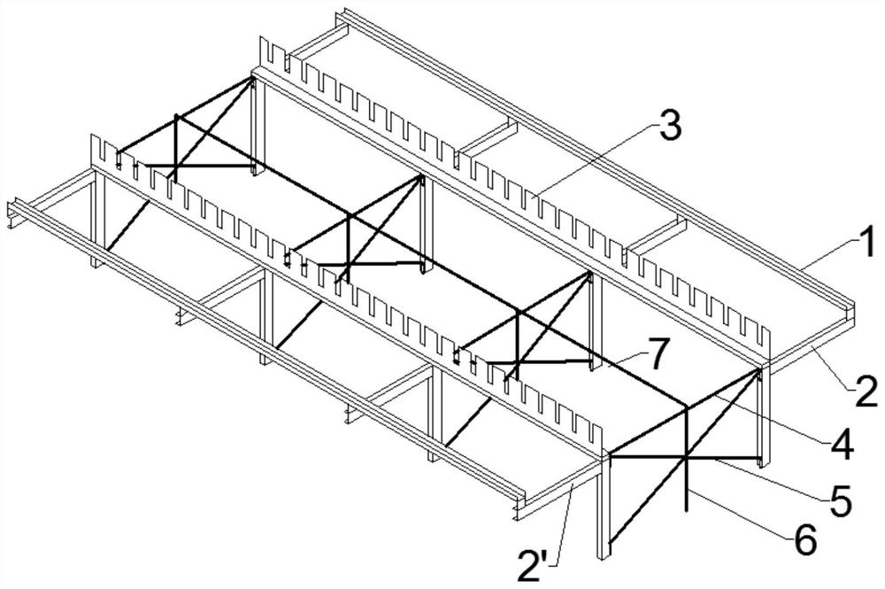
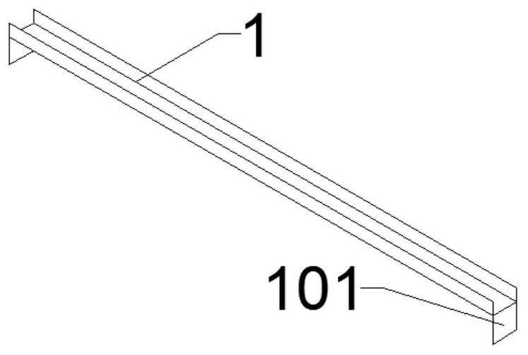
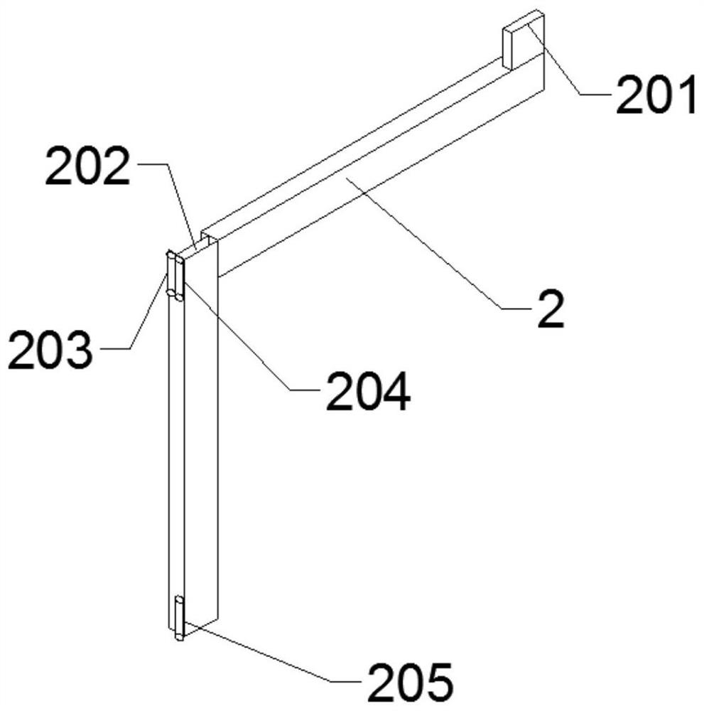
[0031] figure 1 The structure of an exemplary gantry of the present invention is shown, and the gantry is generally composed of four support units, two mutually parallel reinforcing bar limiting members 1, two mutually parallel first reinforcing bar supporting members 3 and a first reinforcing bar supporting member 3. It consists of two steel supporting members 7. Adjacent support units are connected by the steel bar limiting member 1, the first steel support member 3 and the second steel support member 7, and the adjacent support units are preferably separated by 2m. However, those skilled in the art should understand that the structure of the frame for binding the steel frame of the prefabricated box girder roof of the present invention is not limited...


PUM


Abstract

The invention relates to a rack for binding a prefabricated box girder top plate reinforcement cage; the rack comprises at least two support units, two parallel reinforcement limiting components, at least two parallel first reinforcement supporting components and at least one second reinforcement supporting component. Each support unit is of a T-shaped structure, all the support units are arranged side by side, the projections of the support units coincide, and the two reinforcement limiting components are connected to the two transverse ends of each support unit respectively, so that an elongated T-shaped structure is formed. Each first reinforcement supporting component is located between the two reinforcement limiting components and is parallel to the reinforcement limiting components, each first reinforcement supporting component is connected to the support unit, each first reinforcement supporting component is provided with a plurality of steel bar positioning grooves distributed according to preset intervals, and all the steel bar positioning grooves are aligned in the transverse direction and the longitudinal direction; the groove bottom of each steel bar positioning groove, the bottom face of the reinforcement limiting component and the second reinforcement supporting component are located on the same horizontal plane.

Description

technical field [0001] The invention belongs to the technical field of roof reinforcement skeleton binding, and in particular relates to a bench for binding a prefabricated box girder roof reinforcement skeleton. Background technique [0002] In the construction of infrastructure such as highways and bridges, cement reinforcement is a commonly used and extremely important method to ensure the strength of concrete structures. In the bridge structure, due to the relatively large load that the bridge body has to bear, it is necessary to arrange a large number of steel bars in the load-bearing structure to ensure the structural strength of the reinforced concrete. As a rule, a reinforced skeleton is formed by binding. [0003] Generally, the roof reinforcement skeleton is bound directly above the pier base, and then concrete is poured. However, due to the large span between the piers, it is extremely inconvenient to operate. In addition, the reasons for high-altitude operation...

Claims


Application Information

Patent Timeline
Patent Type & Authority Applications(China)
IPC IPC(8): B21F27/08B21F27/20E01D21/00E01D2/04E01D101/26
CPCB21F27/08B21F27/20E01D21/00E01D2/04E01D2101/26
Inventor 吴浩楠孙亚东宋景双刘龙周郭静邓自红康海军李彬彬张国建
Owner HEBEI CONSTR GRP CO LTD
Why Eureka
Try Eureka