Combined gravure rotary press

A printing machine and combined technology, applied in the directions of sending objects, stacking receiving devices, thin material handling, etc., can solve the problems of sub-stack storage and increase the difficulty of storage of printed products, so as to improve the quality, reduce the difficulty of storage, and improve the use of effect of life

Inactive Publication Date: 2022-02-18
陈梦
View PDF0 Cites 0 Cited by
  • Summary
  • Abstract
  • Description
  • Claims
  • Application Information

AI Technical Summary

Problems solved by technology

[0005] Aiming at the deficiencies of the prior art, the present invention provides a combined gravure rotary printing machine, which solves the problem that the printed products after printing in the existing gravure rotary printing machine cannot be automatically stored in piles according to the quality, which increases the difficulty of storing printed products It reduces the wear and tear caused by the friction between the printed product and the device during the moving process, increases the service life of the device, improves the quality of the printed product, and increases the cooling capacity of the device

Method used


Image

  • Combined gravure rotary press
  • Combined gravure rotary press
  • Combined gravure rotary press

Examples


Embodiment 1

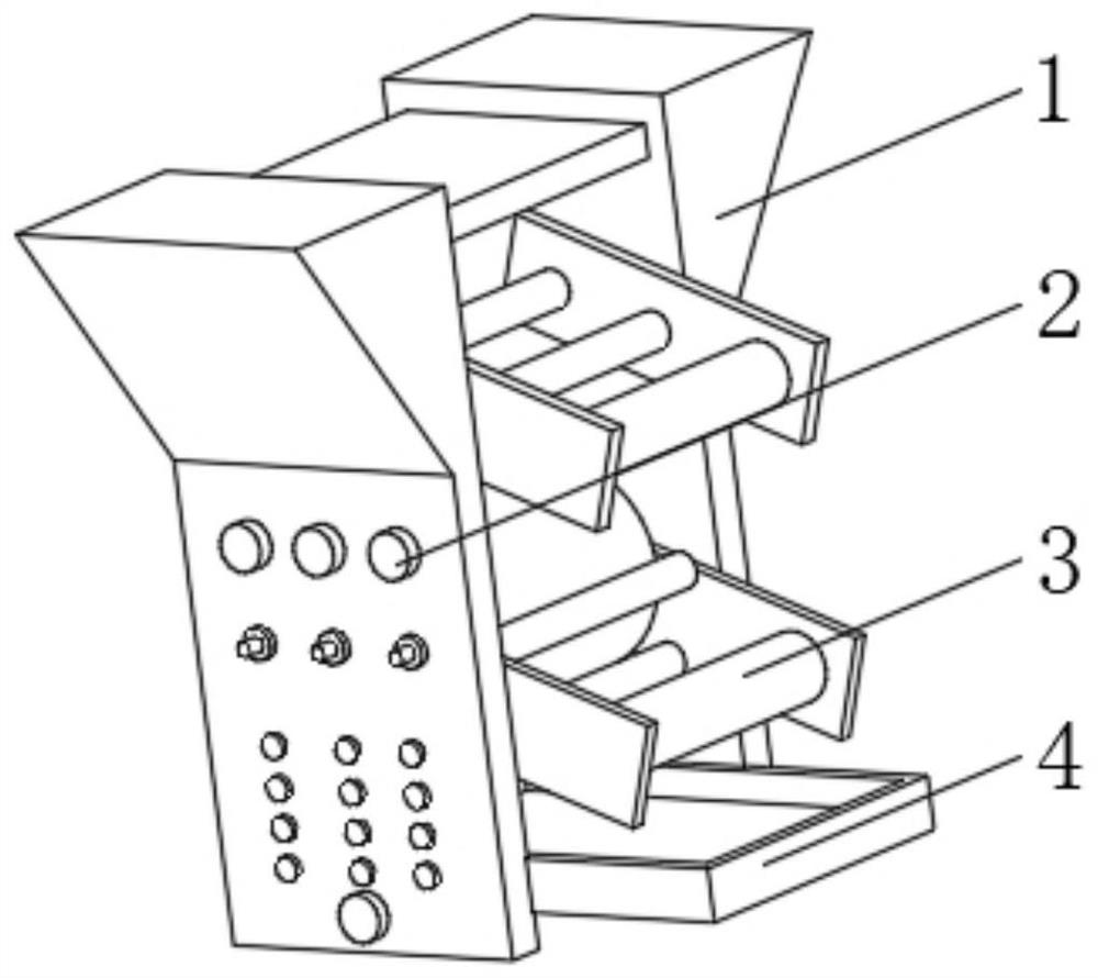
[0033] see Figure 1-4 , the present invention provides a technical solution: a combined gravure rotary printing machine, comprising a printing machine main body 1, a control button 2 is arranged on one side of the printing machine main body 1, a printing roller 3 is arranged on one side of the printing machine main body 1, Between the two sides of the main body 1 of the printing machine, a material receiving box 4 is arranged under the printing roller 3, and the inside of the material receiving box 4 is provided with:

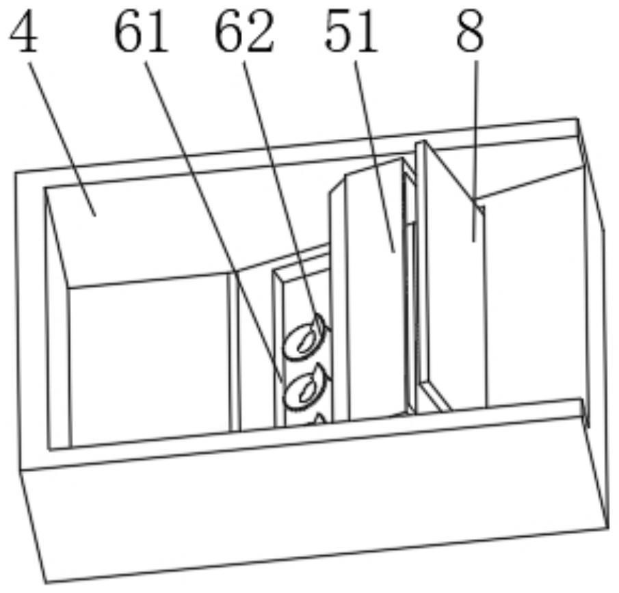
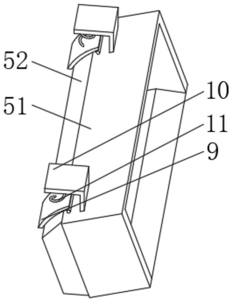
[0034] A shunt device 5, the shunt device 5 has a limiting frame 51, one end of the limiting frame 51 is provided with a rubber ring 52, and the inner top of the rubber ring 52 is symmetrically provided with a protective frame 53;

[0035] The guide device 7 , the guide device 7 has a metal bar 71 , both ends of the metal bar 71 are arc-shaped, and the metal bar 71 is slidably connected to the inner wall of the rubber ring 52 .

[0036] The inner top of the r...

Embodiment 2

[0042] see Figure 1-6 , the present invention provides a technical solution: on the basis of Embodiment 1, a buffer device 6 is provided inside the receiving box 4, and the buffer device 6 has a buffer groove 61, and the inner bottom of the buffer groove 61 is evenly provided with spiral elastic pieces 62 , The top of the helical shrapnel 62 is provided with a ventilation hole 63 .

[0043] An elastic plate 8 is disposed on the inner bottom of the buffer groove 61 , and the elastic plate 8 extends to the outside of the buffer groove 61 and is slidably connected with the limiting frame 51 .

[0044] The inner bottom of the buffer tank 61 is provided with a lifting rod 12 , the lifting rod 12 passes through the air hole 63 and extends above the spiral elastic piece 62 , and the outer side of the lifting rod 12 is provided with an arc-shaped elastic piece 13 .

[0045] The lifting rod 12 runs through the material receiving box 4 and extends to the outside of the material receiv...


PUM


Abstract

The invention discloses a combined type gravure rotary press which comprises a press main body, a control button is arranged on one side of the press main body, a printing roller is arranged on one side of the press main body, a material receiving box is arranged between the two sides of the press main body and located below the printing roller, and a flow dividing device, a buffer device and a flow guiding device are arranged in the material receiving box; and the flow dividing device is provided with a limiting frame, a rubber ring is arranged at one end of the limiting frame, and protective frames are symmetrically arranged on the top of the inner side of the rubber ring. The invention relates to the technical field of printing press. According to the combined type gravure rotary press, the purpose that printed products are automatically stacked and stored according to the quality after printing is completed is achieved, the storage difficulty of the printed products is lowered, abrasion caused by friction between the printed products and the device in the moving process is reduced, the service life of the device is prolonged, the quality of the printed products is improved, and the cooling capability of the device is improved.

Description

technical field [0001] The invention relates to the technical field of printing machines, in particular to a combined gravure rotary printing machine. Background technique [0002] Combined gravure rotary printing machine is an important equipment for light industry production packaging and paper document printing. With the standardization of working environment and machine operation, the quality control of printing in rotary printing plays a pivotal role. Rotary printing machine adopts The most important is the soft pressing design where the rubber cylinders are the impression cylinders, and the paper is rolled by the rubber cylinders to complete the ink transfer. [0003] However, the printed products of the existing gravure rotary printing machine cannot be automatically stored in piles according to the quality, which increases the difficulty of storing the printed products. The printed products are easy to rub against the device during the movement and cause wear, which ...

Claims


Application Information

Patent Timeline
Patent Type & Authority Applications(China)
IPC IPC(8): B65H31/00B65H31/24B65H33/00
CPCB65H31/00B65H31/24B65H33/00B65H2301/5144B65H2701/176B65H2405/1117
Inventor 陈梦
Owner 陈梦
Why Eureka
Try Eureka