
Cross-flow fan and air conditioner

A cross-flow fan and cavity technology, applied in the field of air conditioning devices, can solve the problems of noise increase, large air supply wind resistance of air conditioners, etc., and achieve the effect of reducing air supply wind resistance and noise

Pending Publication Date: 2022-02-18
QINGDAO HAIER SMART TECH R & D CO LTD +1
View PDF0 Cites 0 Cited by
  • Summary
  • Abstract
  • Description
  • Claims
  • Application Information

AI Technical Summary

Problems solved by technology

[0005] Embodiments of the present disclosure provide a cross-flow fan and an air conditioner to solve the problem of high air supply air resistance and increased noise of the air conditioner

Method used


Image

  • Cross-flow fan and air conditioner
  • Cross-flow fan and air conditioner
  • Cross-flow fan and air conditioner

Examples


Embodiment Construction

[0032] In order to understand the characteristics and technical content of the embodiments of the present disclosure in more detail, the implementation of the embodiments of the present disclosure will be described in detail below in conjunction with the accompanying drawings. The attached drawings are only for reference and description, and are not intended to limit the embodiments of the present disclosure. In the following technical description, for purposes of explanation, numerous details are set forth in order to provide a thorough understanding of the disclosed embodiments. However, one or more embodiments may be practiced without these details. In other instances, well-known structures and air conditioners may be shown simplified to simplify the drawings.

[0033] The terms "first", "second" and the like in the description and claims of the embodiments of the present disclosure and the above drawings are used to distinguish similar objects, and are not necessarily used...


PUM


Abstract

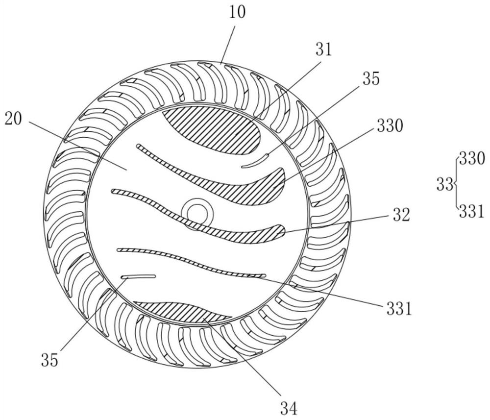
The invention relates to the technical field of air conditioning devices, and discloses an air conditioner which comprises a cross-flow fan, wherein the cross-flow fan comprises an impeller, and a cavity is formed in the impeller; and a flow guide structure which is arranged in the cavity and divides the cavity into a plurality of air channels. According to the cross-flow fan, the flow guide structure is arranged in the cavity in the cross-flow fan, the cavity is divided into the multiple air channels through the flow guide structure, airflow can flow along the air channels after entering the cross-flow fan, and finally flows out of the cross-flow fan, so that airflow guiding is achieved, and air supply resistance and noise of the air conditioner can be reduced.

Description

technical field [0001] The present application relates to the technical field of air conditioning devices, for example, to a cross-flow fan and an air conditioner. Background technique [0002] With the popularization of air conditioners and the promotion of health concepts, users have higher and higher requirements for the comfort of air conditioners. It is hoped that in the heating mode, the hot air is blown to the ground to realize carpet air supply. In the case of carpet-type air supply, hot air is less dense than cold air, and the hot air blowing to the ground will continue to float up, quickly raising the temperature of the room. If the hot air is directly blown to the upper part of the room, the hot air will gather in the upper part and be difficult to sink, and there will be an uncomfortable feeling of warm head and cold feet. It is hoped that in the cooling mode, the cold air is blown to the upper part of the room to realize the shower-style air supply. In the ca...

Claims


Application Information

Patent Timeline
Patent Type & Authority Applications(China)
IPC IPC(8): F24F1/0025F24F13/24F04D29/66
CPCF24F1/0025F24F13/24F04D29/667F24F2013/247
Inventor 王伟徐超田志强李婧田丰顾明亮
Owner QINGDAO HAIER SMART TECH R & D CO LTD
Learn More