Straightening machine and straightening process thereof

A straightening machine and straightening technology, applied in the field of straightening machines, can solve the problems of lower production efficiency, only online cutting, and impact damage of straightening machines, so as to improve the yield and yield, improve production efficiency, Guarantee the effect of production rhythm

Pending Publication Date: 2022-02-22
北京冶自欧博科技发展有限公司
View PDF6 Cites 0 Cited by
  • Summary
  • Abstract
  • Description
  • Claims
  • Application Information

AI Technical Summary

Problems solved by technology

[0002] At present, the upper roll system of the traditional medium and thick plate straightening machine equipment in China can only be adjusted by pressing down as a whole, and the height between the upper straightening rolls is also the same
[0003] In addition, the reduction amount of the leveling machine is adjusted by the overall up and down movement of the upper roller system, and before the steel plate reaches the leveler after finishing rolling and rapid cooling, it is very common that the head is warped. If it is too high, it will hit the entrance guide. In severe cases, the head may be superimposed. In the end, it can only be cut online, which is labor-intensive and time-consuming, and is very inconvenient. Leveler has some impact damage
[0004] In order to improve the quality of the plate shape, the overall tilting of the upper roll system is usually used to adjust the roll gap at the entrance and exit and increase the pressure to eliminate possible steel plate shape defects, and then perform conventional straightening. Although this process can improve the shape quality of the steel plate, However, it affects the production rhythm and reduces production efficiency

Method used


Image

  • Straightening machine and straightening process thereof
  • Straightening machine and straightening process thereof
  • Straightening machine and straightening process thereof

Examples


Embodiment Construction

[0028] The implementation of the present invention will be described in detail below with reference to the drawings and examples.

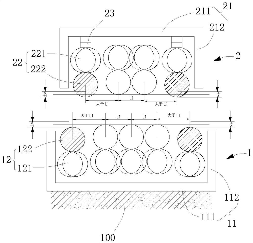
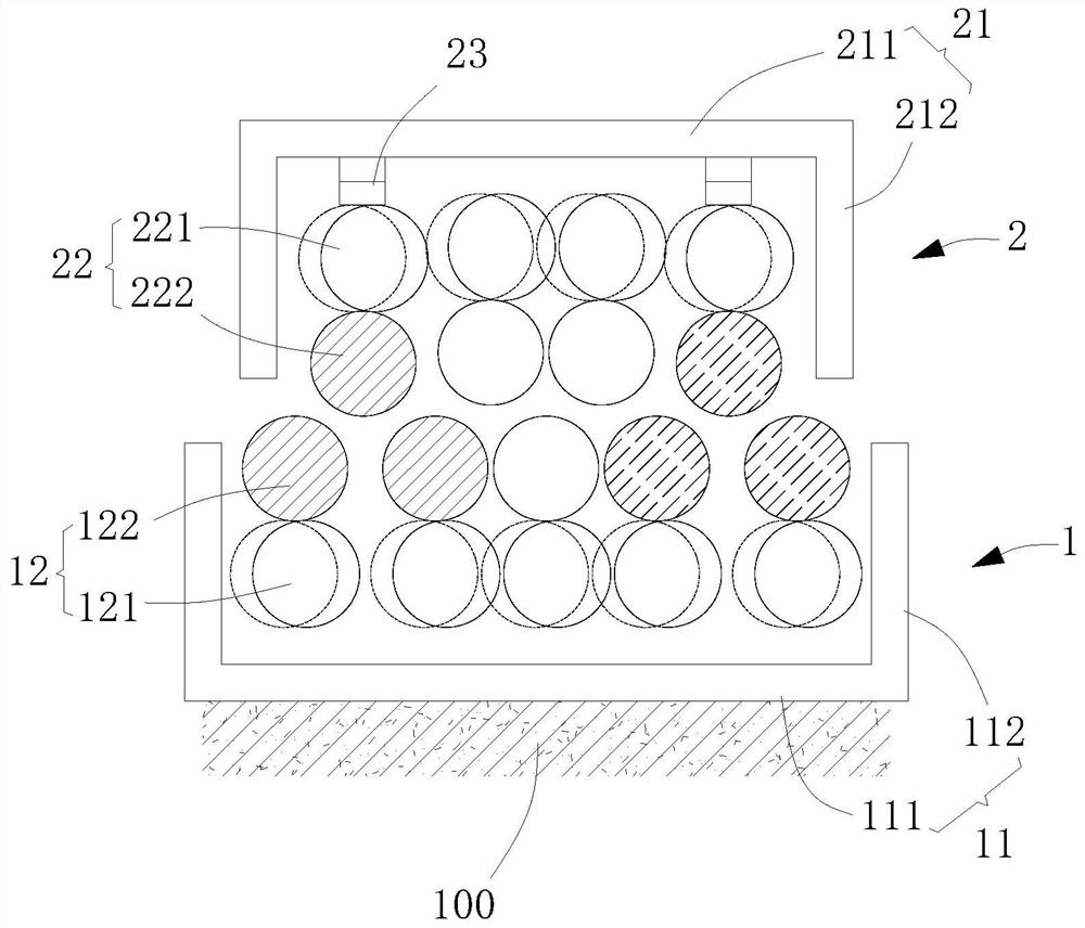
[0029] see Figure 1 to Figure 4 As shown, a straightening machine described in this embodiment includes a lower roller mechanism 1, an upper roller mechanism 2 that is relatively placed on the upper part of the lower roller mechanism 1 and can be raised and lowered relative to the lower roller mechanism 1, and drives the upper roller mechanism 2 to be relatively The hydraulic drive system (not shown) for the lifting of the lower roller mechanism 1 is to cooperate with the upper roller mechanism 1 and the upper roller mechanism 2 to straighten the steel plate.

[0030] The lower roller mechanism 1 is placed on the mounting base 100 , and the lower roller mechanism 1 includes a lower roller box 11 , and a lower roller assembly 12 arranged in the lower roller box 11 and rotatable relative to the lower roller box 11 . The lower roller box 11 include...


PUM


Abstract

The invention relates to a straightening machine which comprises a lower roller mechanism and an upper roller mechanism which is arranged on the upper portion of the lower roller mechanism and can slide relative to the lower roller mechanism, and the lower roller mechanism comprises a plurality of lower supporting rollers and lower straightening rollers correspondingly arranged on the lower supporting rollers. The upper roller mechanism comprises a plurality of upper supporting rollers and upper straightening rollers correspondingly arranged below the upper supporting rollers, the upper straightening rollers and the lower straightening rollers are arranged in a staggered mode, jacking assemblies are correspondingly arranged on the upper portions of the two upper supporting rollers on the two sides, the positions of the upper supporting rollers on the two sides are driven by the jacking assemblies to change, and then the positions of the corresponding upper straightening rollers are changed. And a straightening gap formed between the inlet and the outlet of the straightening machine is adjusted. The invention further relates to a process for independently straightening the steel plate through the side rollers at the two ends of the straightening machine and a straightening process for independently straightening the head or the tail of the steel plate. The straightening machine improves the finished product rate and the yield of steel plates, enables the heads of the steel plates to be straight, improves the production efficiency and guarantees the production rhythm.

Description

technical field [0001] The invention relates to the technical field of straightening machines, in particular to a straightening machine and a straightening process thereof. Background technique [0002] At present, the upper roller system of the existing traditional medium and thick plate straightening machine equipment in China can only be adjusted by pressing down as a whole, and the height between the upper straightening rollers is also the same. [0003] In addition, the reduction amount of the leveling machine is adjusted by the overall up and down movement of the upper roller system, and before the steel plate reaches the leveler after finishing rolling and rapid cooling, it is very common that the head is warped. If it is too high, it will hit the entrance guide. In severe cases, the head may be superimposed. In the end, it can only be cut online, which is labor-intensive and time-consuming, and is very inconvenient. The leveler has some impact damage. [0004] In o...

Claims


Application Information

Patent Timeline
Patent Type & Authority Applications(China)
IPC IPC(8): B21D1/02
CPCB21D1/02
Inventor 马晓明王焜盟王建赵清志林存建李松刘磊杨刚
Owner 北京冶自欧博科技发展有限公司
Why Eureka
Try Eureka