Reinforced concrete partition wall connection node structure

A technology for reinforced concrete and connecting nodes, which is applied in the direction of walls, building components, building structures, etc., can solve the problems of making baffles take a long time, reduce work efficiency, occupy construction time, etc., to shorten the construction period, improve efficiency and strength. enhanced effect

Pending Publication Date: 2022-02-25
何毅
View PDF9 Cites 0 Cited by
  • Summary
  • Abstract
  • Description
  • Claims
  • Application Information

AI Technical Summary

Problems solved by technology

[0003] However, as far as the current traditional partition wall connection nodes are concerned, when connecting at the corners of prefabricated partition walls, in order to ensure the connection strength between prefabricated partition walls, it is necessary to build a separate steel skeleton at the corner, and then connect the steel skeleton with the prefabricated partition. The steel bars of the walls are connected to prevent insufficient strength between the two partition walls at the corner, and building the steel skeleton alone will take up more time for construction, which is troublesome and reduces work efficiency; at the same time, the traditional partition wall connection node is in progress When pouring, the concrete baffles are mostly made of wooden boards nailed together, and most of them are for one-time use. Making the baffles will take a lot of time and cause waste

Method used


Image

  • Reinforced concrete partition wall connection node structure
  • Reinforced concrete partition wall connection node structure
  • Reinforced concrete partition wall connection node structure

Examples


Embodiment

[0037] Example: Please refer to Figure 1 to Figure 11 :

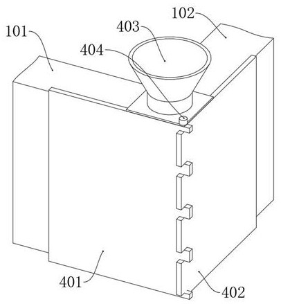
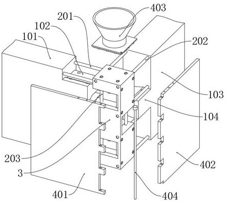
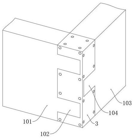
[0038] The present invention proposes a reinforced concrete partition wall connection node structure, comprising: a reinforcement group 2; a wall 1 is poured outside the reinforcement group 2, and a transverse wall 101 of the wall 1 is poured outside the transverse reinforcement 201 of the reinforcement group 2; The intersection of the longitudinal wall 103 and the transverse wall 101 of the wall 1 is poured with concrete blocks 3;

[0039] In addition, according to an embodiment of the present invention, as figure 2 , Figure 5 , Figure 6 As shown, the wall 1 also includes: a fixed block A102; the fixed block A102 is a trapezoidal structure, and two fixed blocks A102 are connected to the right side of the horizontal wall 101; the fixed block A102 cooperates with the fixed block B104 to assist the concrete block 3 fixed to prevent the concrete block 3 from being shaken away from the wall 1 when it is not complete...


PUM


Abstract

The invention provides a reinforced concrete partition wall connecting joint structure, and relates to the technical field of concrete wall structures. The structure comprises a steel bar group; a wall body is poured on the outer side of the steel bar group; a concrete block is poured at the crossed position of the longitudinal wall and the transverse wall of the wall body; a pouring assembly is installed on the outer side of the wall body, fixing steel bars inserted into transverse steel bars and longitudinal steel bars are simply fixed through bundling hoops, and the contact area between the transverse wall and a poured concrete block and between the longitudinal wall and the poured concrete block is greatly increased through a fixing block A and a fixing block B; the adhesive force between the concrete building block and the transverse wall and the longitudinal wall is increased, and the problems that the strength between two partition walls at the corner of an existing traditional partition wall connecting joint is not enough, much construction time is occupied when a steel reinforcement framework is independently built, the trouble is caused, and meanwhile the working efficiency is reduced are solved.

Description

technical field [0001] The invention relates to the technical field of concrete wall structures, in particular to a reinforced concrete partition wall connection node structure. Background technique [0002] In the construction of houses, prefabricated concrete slabs are used to initially erect walls, and then concrete is used to connect the erected prefabricated slabs is a relatively common construction method at present. work efficiency. [0003] However, as far as the current traditional partition wall connection nodes are concerned, when connecting at the corners of prefabricated partition walls, in order to ensure the connection strength between prefabricated partition walls, it is necessary to build a separate steel skeleton at the corner, and then connect the steel skeleton with the prefabricated partition. The steel bars of the walls are connected to prevent insufficient strength between the two partition walls at the corner, and building the steel skeleton alone wi...

Claims


Application Information

Patent Timeline
Patent Type & Authority Applications(China)
IPC IPC(8): E04B2/84
CPCE04B2/84
Inventor 何毅陈宝宪谭铭栎班星杨土能
Owner 何毅
Why Eureka
Try Eureka