One-way self-locking mechanism applied to rotating shaft, motor and linear actuator

A rotating shaft, one-way technology, applied in the direction of brake type, mechanical equipment, etc., can solve the problem of self-locking force drop

Inactive Publication Date: 2022-02-25
ZHEJIANG JIECHANG LINEAR MOTION TECH
View PDF0 Cites 0 Cited by
  • Summary
  • Abstract
  • Description
  • Claims
  • Application Information

AI Technical Summary

Problems solved by technology

The most ideal solution is to have a real one-way self-locking device, especially applied to the shaft body. The existing one-way self-locking mechanism is usually directly sleeved on the shaft body. Once local wear occurs After that, the self-locking force will decrease, and the whole replacement is required

Method used


Image

  • One-way self-locking mechanism applied to rotating shaft, motor and linear actuator
  • One-way self-locking mechanism applied to rotating shaft, motor and linear actuator
  • One-way self-locking mechanism applied to rotating shaft, motor and linear actuator

Examples


Embodiment Construction

[0057] The technical solutions of the embodiments of the present invention will be explained and described below in conjunction with the accompanying drawings of the embodiments of the present invention, but the following embodiments are only preferred embodiments of the present invention, not all of them. Based on the examples in the implementation manners, other examples obtained by those skilled in the art without making creative efforts all belong to the protection scope of the present invention.

[0058] Where words such as "exemplary" and "some embodiments" appear hereinafter, they are meant "serving as examples, embodiments, or illustrations," and any embodiment described as "exemplary" is not necessarily to be construed as superior or better than others. Example. In order to better illustrate the present invention, numerous specific details are given in the following specific embodiments, and those skilled in the art should understand that the present disclosure can al...


PUM


Abstract

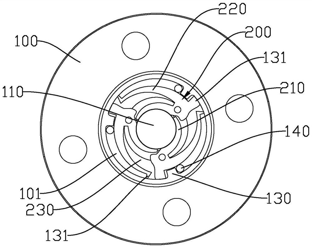
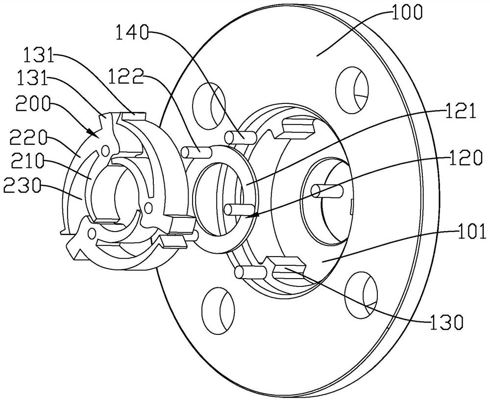
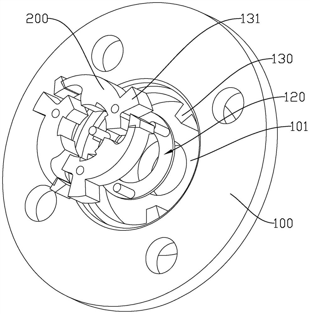
The invention discloses a one-way self-locking mechanism applied to a rotating shaft, a motor and a linear actuator, and belongs to the field of self-locking Mechaniss. The one-way self-locking mechanism applied to the rotating shaft comprises a shell sleeving a rotating shaft multiple friction tiles arranged in the shell and distributed in the circumferential direction of the rotating shaft, a positioning piece used for positioning of the friction tiles to enable the friction tiles to be attached to the rotating shaft and rotate along with the rotating shaft, an extrusion part used for applying an acting force towards the direction of the rotating shaft to the friction tiles, and clamping pieces used for stopping the friction tiles after the friction tiles rotate in place; the contact surface of the friction tile and the extrusion piece is an arc surface, and the radius of the arc surface is gradually increased in the anticlockwise direction, so that the friction force between the friction tile and the rotating shaft is increased when the rotating shaft rotates clockwise.

Description

【Technical field】 [0001] The invention relates to the field of self-locking mechanisms, in particular to a one-way self-locking mechanism, a motor and a linear actuator applied to a rotating shaft. 【Background technique】 [0002] In most of the transmission machinery applications, it is required that the transmission parts can remain static when they stop, to avoid movement due to external force, such as the drive shaft of the motor, so it is necessary to add a self-locking mechanism to the transmission parts. to lock. Although the self-locking structure can generate self-locking force, if the transmission component also has self-locking force during normal operation, it will hinder the movement of the transmission component. The most ideal solution is to have a real one-way self-locking device, especially applied to the shaft body. The existing one-way self-locking mechanism is usually directly sleeved on the shaft body. Once local wear occurs Afterwards, the self-locking...

Claims


Application Information

Patent Timeline
IPC IPC(8): F16D63/00
CPCF16D63/006
Inventor 许欣叶孝东沈如芳
Owner ZHEJIANG JIECHANG LINEAR MOTION TECH
Why Eureka
Try Eureka