
Interference three-dimensional shape calculation method

A three-dimensional shape and calculation technology, applied in the direction of instruments, measuring devices, optical devices, etc., can solve the problem of mixed multi-level interference stray light signals, signal contrast reduction, and difficulty in obtaining high-precision three-dimensional surface topography of the target surface, etc. problems, achieve high fitting accuracy and improve real-time performance

Active Publication Date: 2022-02-25
CHANGCHUN INST OF OPTICS FINE MECHANICS & PHYSICS CHINESE ACAD OF SCI
View PDF5 Cites 0 Cited by
  • Summary
  • Abstract
  • Description
  • Claims
  • Application Information

AI Technical Summary

Problems solved by technology

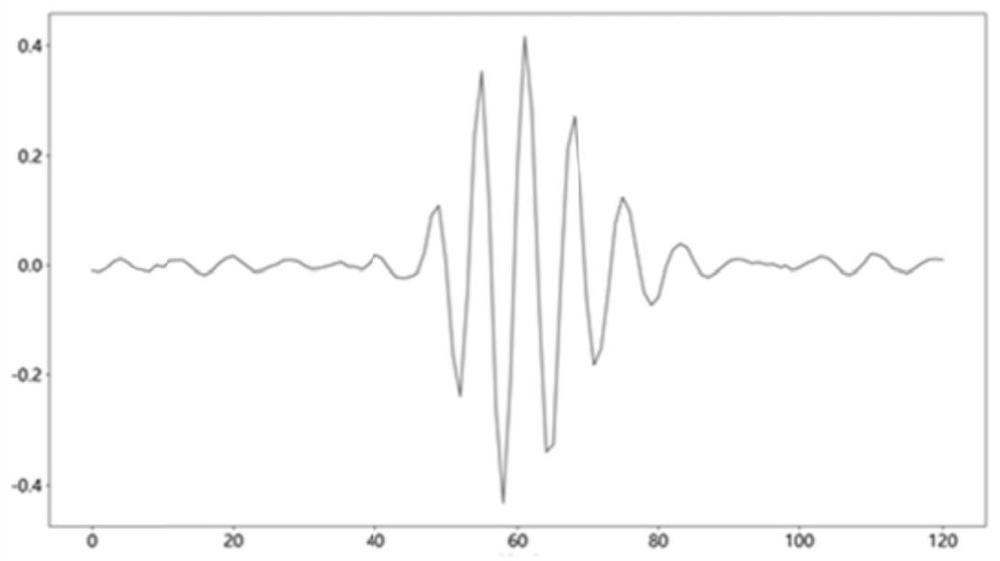
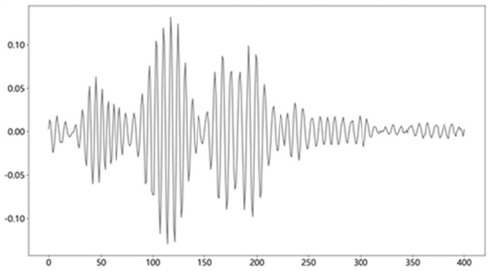
[0006] Each of the above methods will give a near-ideal solution when faced with a perfect signal, but when the spectrally degraded retroreflected signal or the intensity attenuated retroreflected signal generates an interference pattern with the standard reflector's retroreflected signal, it will There will be problems such as broadening of the interference signal envelope curve and decrease in signal contrast. At the same time, multi-level interference stray light signals will be mixed in, which will produce a more degraded interferogram to be processed (such as Figure 2a , Figure 2b shown)
It is difficult to obtain the three-dimensional topography of the target surface with high restoration accuracy by using the above methods

Method used


Image

  • Interference three-dimensional shape calculation method
  • Interference three-dimensional shape calculation method
  • Interference three-dimensional shape calculation method

Examples


Embodiment Construction

[0069] In order to make the object, technical solution and advantages of the present invention clearer, the present invention will be further described in detail below in conjunction with the accompanying drawings and specific embodiments. It should be understood that the specific embodiments described here are only used to explain the present invention, but not to limit the present invention.

[0070] The object of the present invention is to provide a method for calculating an interference three-dimensional shape. The method for calculating an interference three-dimensional shape provided by the present invention will be described in detail below through specific embodiments.

[0071] In the conventional white light interferogram, due to factors such as "multiple interference superposition effect" and "spectral degradation effect", the top peak Z of the outer envelope curve d and the center position Z of the zero-order interference fringe (sub-envelope curve) 0 Often do not...


PUM


Abstract

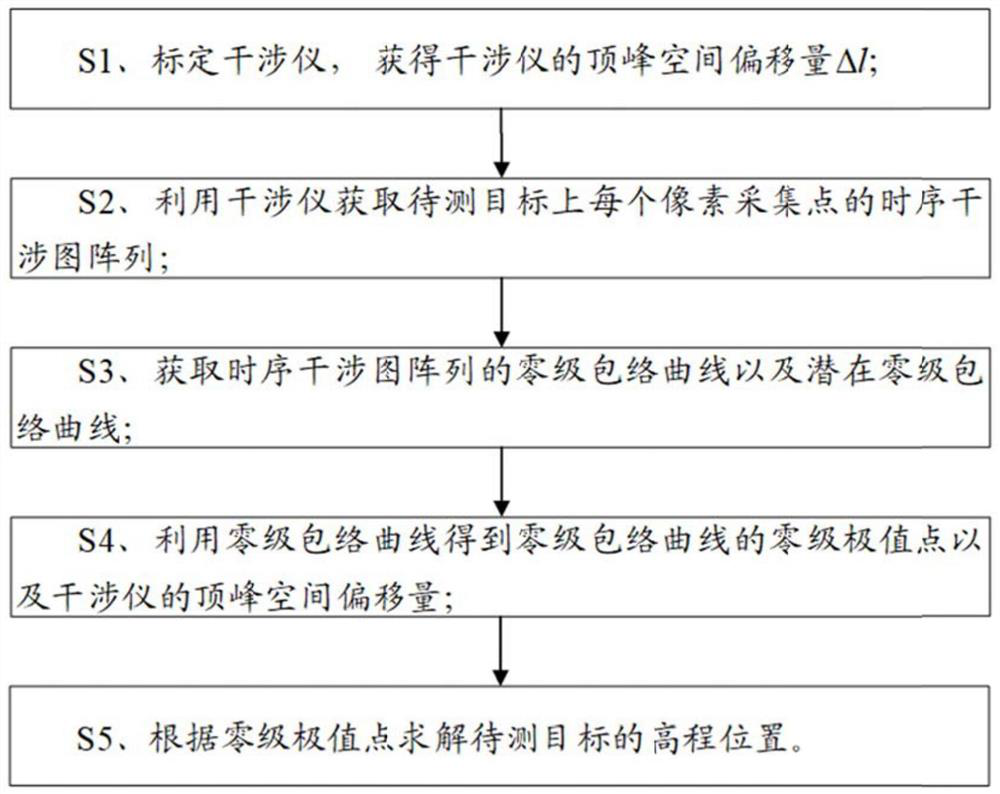
The invention provides an interference three-dimensional shape resolving method, which comprises the steps of S1, calibrating an interferometer to obtain a peak space offset delta l of the interferometer; S2, acquiring a time sequence interferogram array of each pixel acquisition point P (xi, yj) on aa target to be measured by using the interferometer, wherein the time sequence interferogram array is N interference images with interference fringes; S3, acquiring a zero-order envelope curve and a potential zero-order envelope curve of the time sequence interferogram array; S4, obtaining a zero-order extreme point Z0 (xi, yj) of the zero-order envelope curve by using the zero-order envelope curve; and S5, solving the elevation position Zd (xi, yj) of the target to be measured according to the zero-order extreme point Z0 (xi, yj). The method is carried out in the airspace, the frequency domain large calculation amount processes such as Fourier transform and convolution are avoided, and the real-time performance of the algorithm is improved; and the method has high fitting precision through fitting of the sub-envelope curves, and can be used for three-dimensional shape calculation of the surface of a low-reflectivity object.

Description

technical field [0001] The invention belongs to the technical field of surface topography measurement, and in particular relates to an interference three-dimensional topography solution method. Background technique [0002] In the existing technology, many scholars have carried out a series of research work on the problem of white light interferogram calculation, and these research work can be summarized into three main technical development directions: [0003] 1. Direct solution method, specifically including interpolation method, phase shifting method, space frequency domain method; [0004] 2. Weighted average method, specifically including center of gravity method and coherent correlation method; [0005] 3. Envelope curve fitting method, specifically including polynomial fitting method, Gaussian fitting method, Fourier transform method, Hilbert transform method, wavelet transform method, envelope curve function calculation method based on sampling theorem. [0006] I...

Claims


Application Information

Patent Timeline
IPC IPC(8): G01B11/24
CPCG01B11/2441
Inventor 姚东梁瀚钢
Owner CHANGCHUN INST OF OPTICS FINE MECHANICS & PHYSICS CHINESE ACAD OF SCI
Learn More