
Transportation pipeline vibration pick-up leakage detection method based on low-reflection chirp grating array

A chirped grating and low-reflection technology, applied in the field of pipeline leakage detection, can solve the problems of difficulty in implementation and monitoring accuracy, and achieve the effect of easy implementation, easy implementation, and improved judgment steps

Active Publication Date: 2022-02-25
WUHAN UNIV OF TECH
View PDF6 Cites 0 Cited by
  • Summary
  • Abstract
  • Description
  • Claims
  • Application Information

AI Technical Summary

Problems solved by technology

[0006] The purpose of the present invention is to overcome the defects and problems existing in the prior art that it is difficult to take into account the difficulty of implementation and the accuracy of monitoring, and to provide a pick-up device for transportation pipelines based on a low-reflection chirped grating array that has high monitoring accuracy and easy implementation. Vibration leak detection method

Method used


Image

  • Transportation pipeline vibration pick-up leakage detection method based on low-reflection chirp grating array
  • Transportation pipeline vibration pick-up leakage detection method based on low-reflection chirp grating array
  • Transportation pipeline vibration pick-up leakage detection method based on low-reflection chirp grating array

Examples


Embodiment 1

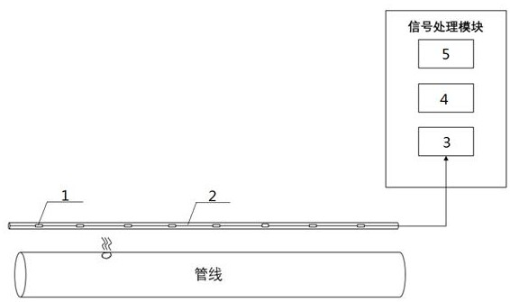
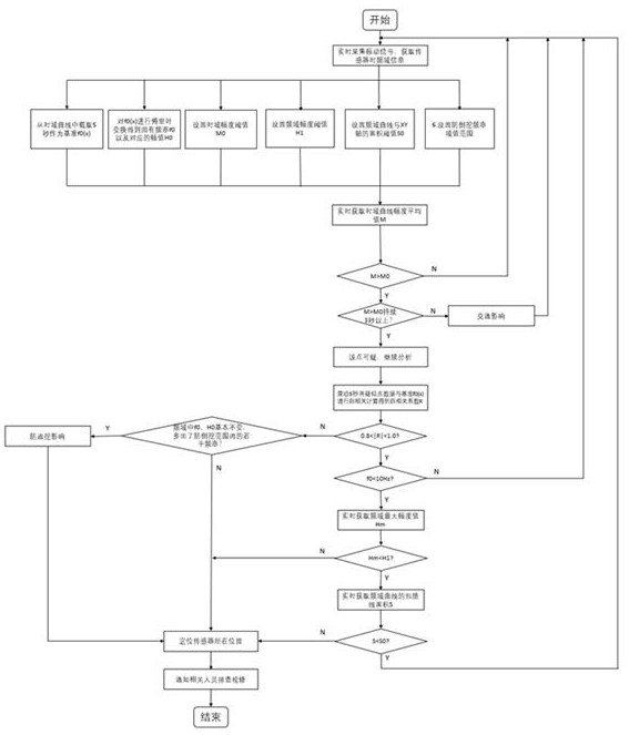
[0078] See figure 1 and figure 2 , A transmission conduit pick-up leak detection method based on a low reflection 啁 光 grating array, including the sensing fiber optic cable laying process, database setting process, signal analysis process;

[0079] The sensing fiber optic cable laying process includes: first set a plurality of vibration sensors 1 in the internal interval of the weak light gate array sensing cable 2, the vibration sensor 1 is made of a 啁啾 grating, and a weak grating array is transmitted. The optical cable 2 is paved over the tube of the pipe axis, and then signals the end of the weak light gate array sensing cable 2 to one end of the fiber grating demodulator 3, and the other end of the fiber grating demodulator 3. A terminal display 5 is connected to the computer 4 and a terminal display 5 is connected to the computer 4;

[0080] The database setting process includes: When the pipe has no leakage, when each vibration sensor 1 is acquired, the frequency domain info...

Embodiment 2

[0084] Basic content is the same as in Example 1. The difference is:

[0085] Preferably, M0 = (1.1-1.3) * mA, the H1 = (1.1-1.3) * H0, the S0 = (1.1-1.3) * SA. Further preferred M0 = 1.2 * mA, the H1 = 1.2 * H0, the S0 = 1.2 * SA.

Embodiment 3

[0087] Basic content is the same as in Example 1. The difference is:

[0088] It is preferred to have a predetermined period of 5 seconds, 10 seconds, 20 seconds, 30 seconds, 40 seconds, 60 seconds.


PUM


Abstract

The invention provides a transportation pipeline vibration pick-up leakage detection method based on a low-reflection chirp grating array. The method comprises the steps that a plurality of vibration sensors are sequentially arranged in a weak grating array sensing optical cable at equal intervals, wherein the vibration sensors are made of chirp gratings; the weak grating array sensing optical cable is laid above a to-be-detected pipeline in a direction parallel to the axis of the pipeline; the tail end of the weak grating array sensing optical cable is in signal connection with a computer through a fiber grating demodulator; time domain information and frequency domain information of each vibration sensor are obtained and recorded under the condition that the pipeline is free of leakage to form a database; then the real-time time domain information and the real-time frequency domain information of each vibration sensor are compared with time domain information and frequency domain information recorded in the database to conduct leakage judgment, and if it is judged that leakage happens to a monitoring point corresponding to the vibration sensor, the specific position of the vibration sensor is positioned, and then troubleshooting and overhauling are conducted. According to the invention, the design is not only high in monitoring precision, but also easy to implement.

Description

Technical field [0001] The present invention relates to a method of transporting a pipeline pick-up leak detection method, which belongs to the technical field of pipeline leakage detection, in particular a transmission conduit pickup leak detection method based on a low reflection 啁 光 grating array. Background technique [0002] Pipe transport is one of the five major transportation methods. For long-distance delivery of liquid and gas materials, mainly including media such as oil, natural gas, playing a pivotal role in national development. Therefore, security is the life of pipe transportation. Pipeline leaks are the main factors affecting pipeline safety, and the corrosion of pipelines, and sudden natural disasters (such as earthquakes, landslides, river flushing) and human destruction will cause pipeline leaks and even rupture, directly threaten the safe operation of long-distance pipelines. . [0003] In recent years, there have been happening in the incident of pipelines, ...

Claims


Application Information

Patent Timeline
Patent Type & Authority Applications(China)
IPC IPC(8): G01M3/24F17D5/02
CPCG01M3/243F17D5/02
Inventor 甘维兵王宇张翠周爱郭会勇
Owner WUHAN UNIV OF TECH
Learn More