Electric permanent magnetic chuck controller with circuit break protection structure

A technology of electric permanent magnetic chuck and permanent magnetic chuck, which is applied to the structural parts of electrical equipment, electrical components, electrical equipment shells/cabinets/drawers, etc., which can solve the internal overall mess, lack of good line collection and fixed structure, etc. problem, achieve the effect of preventing open circuit and improving stability

Active Publication Date: 2022-02-25
南通茂业电子科技有限公司
View PDF10 Cites 1 Cited by
  • Summary
  • Abstract
  • Description
  • Claims
  • Application Information

AI Technical Summary

Problems solved by technology

The electric permanent magnet chuck controller of the present invention can realize the normal magnetization and demagnetization operations of the electromagnetic chuck, and has two detection circuits and protection functions of load short circuit and open circuit detection, overcurrent detection, safe and reliable, and can effectively protect the circuit and Electromagnetic sucker; the pulse voltage for charging and demagnetizing the sucker is easy to obtain, and the charging and demagnetizing effects are remarkable, simple and practical", but the device does not have a good line collection and fixing structure, which makes the interior overall messy, which affects the use

Method used


Image

  • Electric permanent magnetic chuck controller with circuit break protection structure
  • Electric permanent magnetic chuck controller with circuit break protection structure
  • Electric permanent magnetic chuck controller with circuit break protection structure

Examples


Embodiment 1

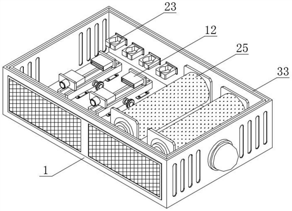
[0042] see figure 2 , Figure 5 , Image 6 with Figure 7 , an embodiment provided by the present invention: an electric permanent magnet chuck controller with an open circuit protection structure, including a permanent magnet chuck controller body 1, an alarm assembly 2 and a fixed slide rail 3, and a permanent magnet chuck controller body 1 An alarm assembly 2 is installed in the middle of one side, and a fixed slide rail 3 is arranged inside the permanent magnetic sucker controller body 1; the front and rear ends of both sides of the fixed slide rail 3 are equipped with connectors 4, and the fixed slide rail 3 The two sides of the fixed slide rail 3 are screwed to the inner bottom wall of the permanent magnet chuck controller body 1 through the connecting piece 4; the front end and the rear end of the top of the fixed slide rail 3 are provided with a limit chute 5, and the inside of the limit chute 5 is slidably connected There is a connecting rod 6, and the middle part...

Embodiment 2

[0045] see figure 1 with Figure 4 , an embodiment provided by the present invention: an electric permanent magnet chuck controller with an open circuit protection structure, including an alarm assembly 2, a connecting rod 14 is installed on one side of the permanent magnet chuck controller body 1, and the connecting rod 14 A heat-absorbing copper plate 15 is installed on the top of the heat-absorbing copper plate 15, and the middle part of the back of the heat-absorbing copper plate 15 is provided with a heated expansion block 16. The surface of the heated expansion block 16 is provided with a touch switch a17, and the middle part of the inner wall of the permanent magnet chuck controller body 1 is provided with a touch switch. The switch b18, and the touch switch a17, the touch switch b18 and the alarm component 2 are all electrically connected;

[0046] Through the setting of the alarm assembly 2, when the staff needs to be provided with an alarm structure to the device, t...

Embodiment 3

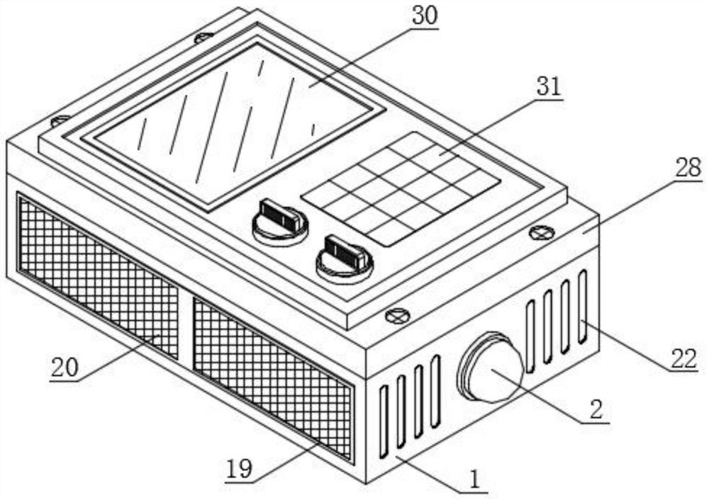
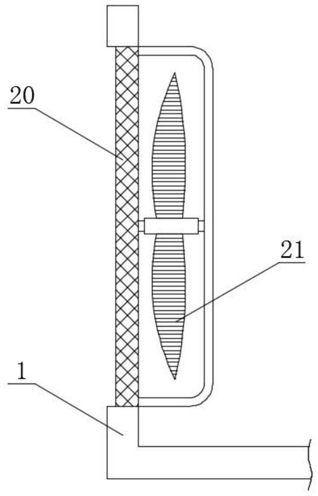
[0048] see figure 2 with image 3 , an embodiment provided by the present invention: an electro-permanent magnet chuck controller with an open circuit protection structure, including a ventilation slot 19, the surface of the permanent magnet chuck controller body 1 is provided with a ventilation slot 19, and the inner wall of the ventilation slot 19 is set There is a dust-proof net 20, and the interior of the permanent magnet chuck controller body 1 is provided with a cooling fan 21, and the cooling fan 21 is located directly behind the ventilation groove 19, and both sides of the permanent magnet chuck controller body 1 are provided with ventilation strips 22;

[0049] Through the setting of the ventilation groove 19, when the staff needs to dissipate heat inside the device, the cooling fan 21 is located directly behind the ventilation groove 19, and both sides of the permanent magnet chuck controller body 1 are provided with ventilation strips 22, and the ventilation groove...


PUM


Abstract

The invention discloses an electric permanent magnetic chuck controller with a circuit break protection structure. The controller comprises a permanent magnetic chuck controller body, an alarm assembly and a fixed slide rail. The alarm assembly is mounted in the middle of one side of the permanent magnetic chuck controller body, and the fixed slide rail is arranged in the permanent magnetic chuck controller body; and connecting pieces are installed at the front ends and the rear ends of the two sides of the fixed sliding rail correspondingly. Through the arrangement of a fixed sliding rail, a junction box a and a junction box b and the matched work of a limiting sliding groove, a good limiting effect can be achieved for a connecting rod, through the matched work of a gear column, a main track shoe, an auxiliary track shoe, a transmission rod and an adjusting knob, the gear column can be driven to rotate through the transmission rod, the gear column can be meshed with the top and the bottom of the surface of the main track shoe and the auxiliary track shoe so as to approach the middle, and the junction box a and the junction box b are matched to work so that the junction box a and the junction box b can play a better role in fixing the electric wire, the overall stability of the device is improved, and the phenomenon of open circuit can be effectively prevented.

Description

technical field [0001] The invention relates to the technical field of electro-permanent magnet chuck controllers, in particular to an electro-permanent magnet chuck controller with an open circuit protection structure. Background technique [0002] The electronically controlled permanent magnet chuck is a new type of fixture designed and developed in combination with the characteristics of electromagnetic and permanent magnets. It adopts a new type of magnetic chuck that uses electric pulses to "open and close". It is very safe and reliable during the process of holding the workpiece. After the workpiece is held by the magnetic force, the suction cup will maintain the magnetic suction indefinitely. It is widely used in CNC machining centers, milling machines, engraving machines, etc., but the existing electric permanent magnet The sucker controller still has certain deficiencies in actual use. [0003] The defective of existing a kind of electropermanent magnetic sucker co...

Claims


Application Information

Patent Timeline
IPC IPC(8): H05K5/02H05K7/20B65H75/44
CPCH05K5/0217H05K7/2039H05K7/20181H05K7/20136B65H75/44
Inventor 王国荣
Owner 南通茂业电子科技有限公司
Why Eureka
Try Eureka