
Heat dissipation device and manufacturing method thereof

A technology of heat dissipation device and manufacturing method, which is applied in the direction of cooling/ventilation/heating transformation, electrical equipment structural parts, electrical components, etc., and can solve the problems of insufficient heat dissipation, poor heat transfer effect in the top area of ​​fins, and increased power consumption. major issues

Active Publication Date: 2022-02-25
HUAWEI TECH CO LTD
View PDF25 Cites 2 Cited by
  • Summary
  • Abstract
  • Description
  • Claims
  • Application Information

AI Technical Summary

Problems solved by technology

However, with the intelligentization of electronic equipment, the power consumption of electronic equipment in vehicles has increased dozens of times, while the heat exchange area of ​​traditional vehicle radiators is obviously insufficient
If you want to increase the heat exchange area of ​​the radiator, you need to increase the height of the radiator fins. However, the higher the fins, the greater the temperature difference from the root to the top of the fins. The heat transfer effect in the top area of ​​the fins is very poor, resulting in The overall utilization efficiency of the chip is poor, and the heat dissipation effect that meets the demand cannot be achieved.

Method used


Image

  • Heat dissipation device and manufacturing method thereof
  • Heat dissipation device and manufacturing method thereof
  • Heat dissipation device and manufacturing method thereof

Examples


Embodiment Construction

[0042] The technical solutions in the embodiments of the present application will be described below with reference to the drawings in the embodiments of the present application.

[0043] The traditional air-cooled radiator mainly rotates the fan to accelerate the air circulation, so as to dissipate the heat as soon as possible. If you want to improve its heat dissipation effect, you can achieve it in the following ways.

[0044] The first way is to increase the heat exchange capacity of the radiator by increasing the rotational speed of the fan, but this improvement is not significant, and may also cause heat generation problems of the radiator itself. In addition, it will also bring about a significant increase in noise. If it is installed in a relatively closed environment such as a car, the user experience will be poor.

[0045] The second way is to increase the thickness of the fins. After the thickness of the fins increases, the thermal resistance from the root to the to...


PUM


Abstract

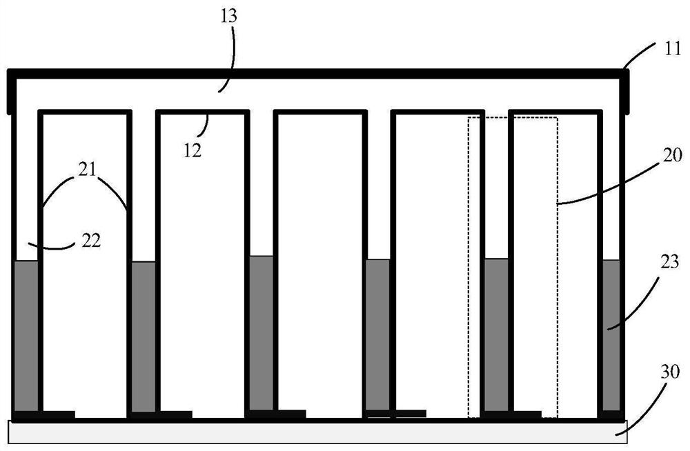
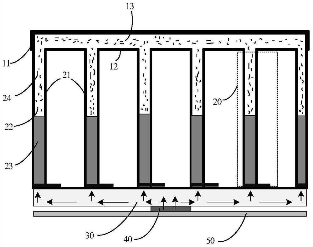
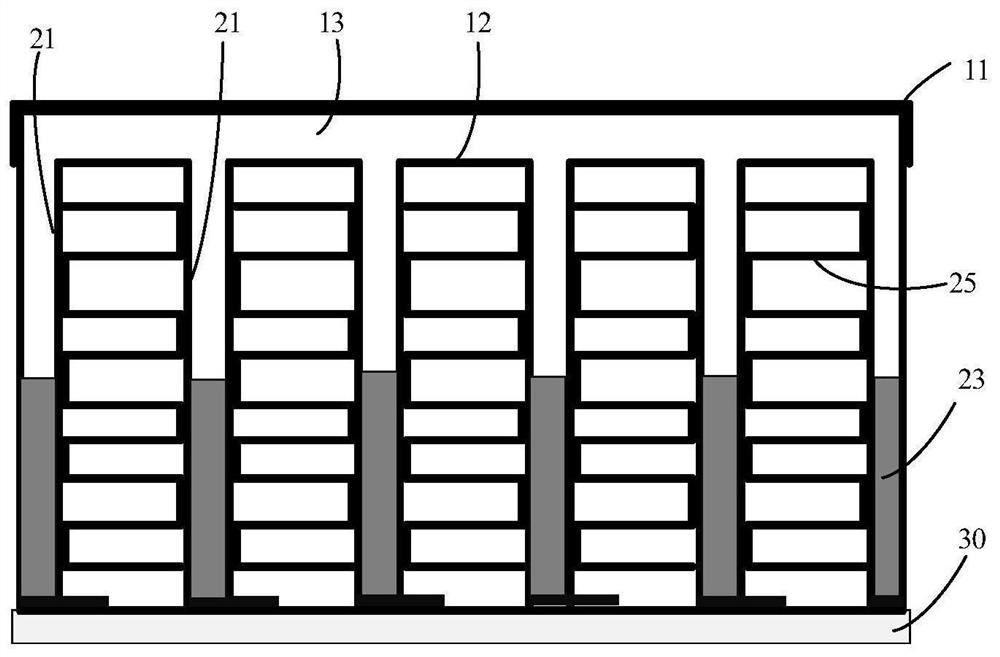
The invention provides a heat dissipation device and a manufacturing method thereof, relates to the technical field of hardware heat dissipation, and the device and method can be applied to small computing equipment configured in an intelligent automobile, an automatic driving automobile, a connected automobile or an electric automobile. The heat dissipation device comprises a top layer, a plurality of thermosyphon flat plate PTS structures and a bottom substrate, the PTS structures are arranged between the top layer and the bottom substrate and are perpendicular to the top layer and the bottom substrate, and second cavities, defined by side walls, of the PTS structures are communicated through first cavities of the top layer; and a refrigerant is filled in each second cavity. According to the heat dissipation device, the special heat dissipation structure of the PTS structure is utilized, and the heat dissipation effect of the heat dissipation device can be remarkably improved. In addition, due to the fact that the cavities of all the PTS structures are communicated, the temperature of steam in the cavities of all the PTS structures tends to be consistent, and the heat dissipation performance of the heat dissipation device can be effectively improved.

Description

technical field [0001] The present application relates to the technical field of hardware heat dissipation, and more particularly, to a heat dissipation device and a manufacturing method thereof. Background technique [0002] With the continuous development of automotive intelligent technology, various electronic devices are used in vehicles, especially for self-driving vehicles, which involve many intelligent devices / systems, and the heat dissipation problem of these electronic devices during the working process is thus highlighted. . Traditional car radiators usually have a dustproof, waterproof, and anti-corrosion aluminum radiator. Some electronic devices with low power consumption can use natural heat dissipation, while some electronic devices with high power consumption will use air cooling to dissipate heat. However, with the intelligentization of electronic equipment, the power consumption of electronic equipment in vehicles has increased dozens of times, and the he...

Claims


Application Information

Patent Timeline
IPC IPC(8): H05K7/20
CPCH05K7/20881H05K7/20854Y02D10/00
Inventor 彭耀锋
Owner HUAWEI TECH CO LTD
Learn More