Supporting seat between rotary tillage shafts and rotary cultivator

A technology of bearing seat and rotary tiller, which is applied in the direction of tillage machines, agricultural machinery and implements, harvesters, etc. It can solve the problems that the rotary tiller cannot be installed, the soil cannot be crushed by the rotary tiller, and the rotary tiller shaft is broken.

Pending Publication Date: 2022-03-01
戴红亮
View PDF0 Cites 0 Cited by
  • Summary
  • Abstract
  • Description
  • Claims
  • Application Information

AI Technical Summary

Problems solved by technology

Because the rotary tiller has a small tillage width and a short rotary tiller shaft, the rotary tiller shaft will not break. The lengthening, the problem brought about by this is that the rotary tiller shaft will break
[0003] figure 2 It is a schematic diagram of a technical measure taken by some manufacturers to solve the problem of broken rotary tillage shafts, that is, a side gearbox is installed on both sides of the frame, and each side gearbox drives a rotary tiller shaft. The frame of the cultivator is equipped with a supporting plate, and the supporting plate is used to support the bearing housings of the two rotary tilling shafts. This solves the problem of fracture caused by the rotary tilling shaft being too long, but this structure also produces another problem, It is precisely because of the existence of the support plate that the rotary tiller cannot be installed at the support plate, so that the upper soil at the support plate cannot be crushed by the rotary tiller, and the crop straw at the support plate cannot be shredded by the rotary tiller. field
[0004] Figure 7 It is a schematic diagram of another technical measure taken by some manufacturers to solve the fracture of the rotary tiller shaft. A side gear box is installed on one side of the rotary tiller frame, and a support plate is set on the rotary tiller frame. The shaft is divided into two or more sections, which also solves the problem of fracture due to the too long rotary tillage shaft, but this method for solving the fracture of the rotary tillage shaft also produces another problem, that is, because of the existence of the support plate, the The rotary tiller cannot be installed on the support plate, the soil on the support plate cannot be crushed by the rotary tiller, and the crop straw on the support plate cannot be chopped by the rotary tiller and returned to the field

Method used


Image

  • Supporting seat between rotary tillage shafts and rotary cultivator
  • Supporting seat between rotary tillage shafts and rotary cultivator
  • Supporting seat between rotary tillage shafts and rotary cultivator

Examples


Embodiment 1

[0050] Such as Figure 11 to Figure 22 As shown, the support seat between the rotary tiller shafts of the present invention includes the installation end 2-6-1 arranged on the rotary tiller frame and the installation end 2-6-2 of the bearing seat, and the installation end 2 of the bearing seat 2 -6-2 is provided with bolt holes 2-6-2-1 (see Figure 11 ), or the mounting end 2-6-2 of the bearing seat is provided with a bolt hole 2-6-2-1 and a passing hole 2-6-2-2 for the transition shaft (see Figure 17 ); a trapezoidal step 2-6-4 or a groove is arranged between the installation end 2-6-1 of the rotary tiller frame and the installation end 2-6-2 of the bearing seat (see Figure 13 and Figure 22 ).

[0051] Further, the trapezoidal steps 2-6-4 or grooves arranged between the installation end of the rotary tiller frame and the installation end of the bearing seat are arc-shaped (such as Figure 16 and Figure 22 ).

Embodiment 2

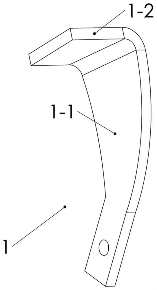
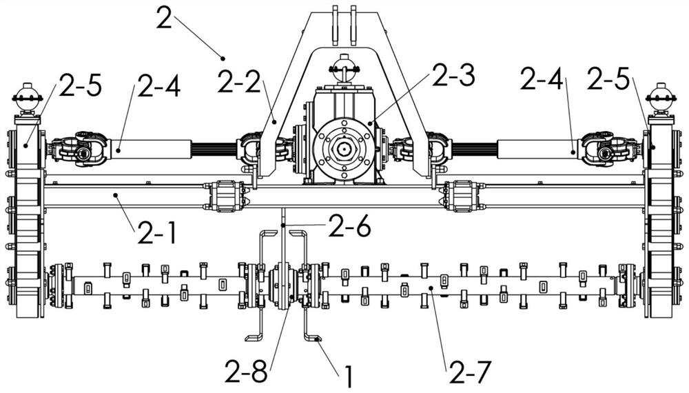
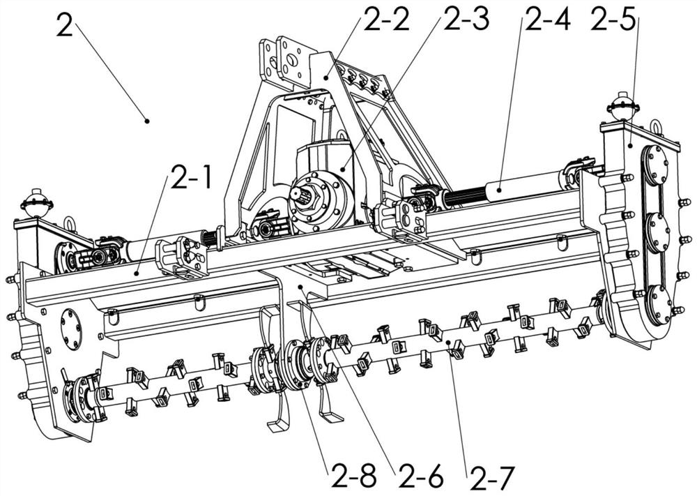
[0053] Such as Figure 11 , Figure 20 , Figure 24 and Figure 25 As shown, the rotary tiller of the present invention includes bearing seats between rotary tiller shafts (see Figure 11 and Figure 20 ), including the installation end 2-6-1 arranged on the rotary tiller frame and the installation end 2-6-2 of the bearing seat, the installation end 2-6-2 of the bearing seat is provided with a bolt hole 2-6 -2-1 (see Figure 11 ), or the mounting end 2-6-2 of the bearing seat is provided with a bolt hole 2-6-2-1 and a through hole 2-6-2-2 of the transition shaft (see Figure 20 ); a trapezoidal step 2-6-4 or a groove is arranged between the installation end 2-6-1 of the rotary tiller frame and the installation end of the bearing seat (see Figure 12 and Figure 21 ), on the rotary tiller shaft 2-7, the rotary tiller blade 1-2 of the rotary tiller is provided with the trapezoidal step 2-6-4 or the groove on the supporting seat between the rotary tiller to match the rotar...


PUM


Abstract

The invention discloses a bearing seat between rotary tillage shafts and a rotary cultivator, belongs to the field of agricultural machinery, and aims to solve the problems that the rotary tillage shafts of the conventional rotary cultivator are broken, soil at a bearing plate cannot be crushed by a rotary blade, and straws of crops cannot be cut and returned to the field by the rotary blade. Comprising a mounting end arranged on a rack of the rotary cultivator and a mounting end of a bearing seat, the mounting end of the bearing seat is provided with a bolt hole, or the mounting end of the bearing seat is provided with a bolt hole and a passing hole of a transition shaft. Trapezoidal steps or grooves are arranged between the mounting end of the rack of the rotary cultivator and the mounting end of the bearing seat, the trapezoidal steps or the grooves are arc-shaped, and the rotary tillage shaft is provided with a soil returning blade part of the rotary tillage blade and the rotary tillage blade which is matched with the trapezoidal steps or the grooves on the bearing seat between the rotary tillage shafts. The soil at the supporting seat between the rotary tillage shafts is crushed by the rotary tillage cutter, and straws of crops can be cut and returned to the field by the soil returning cutting edge part of the rotary tillage cutter.

Description

technical field [0001] The invention relates to a support seat between rotary tiller shafts and a rotary tiller. Background technique [0002] The rotary tiller shafts of present small-sized rotary tillers all have one end connected to the power output shaft of the gear box, and the other end is connected to the bearing seat of the side plate of the rotary tiller. Because the rotary tiller has a small tillage width and a short rotary tiller shaft, the rotary tiller shaft will not break. The lengthening, the problem that brings like this is that the rotary tiller shaft will break. [0003] figure 2 It is a schematic diagram of a technical measure taken by some manufacturers to solve the problem of broken rotary tillage shafts, that is, a side gearbox is installed on both sides of the frame, and each side gearbox drives a rotary tiller shaft. The frame of the cultivator is equipped with a supporting plate, and the supporting plate is used to support the bearing housings of ...

Claims


Application Information

Patent Timeline
Patent Type & Authority Applications(China)
IPC IPC(8): A01B33/08A01B33/10A01B33/02A01D82/00
CPCA01B33/082A01B33/103A01B33/021A01D82/00
Inventor 戴红亮
Owner 戴红亮
Why Eureka
Try Eureka