Wing leading edge structure, forming mold and preparation method thereof for micro-miniature unmanned aerial vehicle

A micro-wing technology, applied in the field of drones, can solve the problems of increasing workload, thickening, increasing structural weight and production and processing workload, so as to reduce the weight of thickening and reduce the workload of grinding Effect

Active Publication Date: 2021-12-21
NANJING UNIV OF AERONAUTICS & ASTRONAUTICS
View PDF0 Cites 0 Cited by
  • Summary
  • Abstract
  • Description
  • Claims
  • Application Information

AI Technical Summary

Problems solved by technology

Adopting the leading edge structure of the airfoil needs to spread the cloth layer after the upper and lower wall panels are glued together to increase the effect of the leading edge bonding. When the gel coat has been sprayed, it is necessary to spray the surface after patching, which destroys the beauty and smoothness of the overall appearance and increases the workload. In addition, the leading edge of the wing surface and the lower wall is partially thickened, which also increases the structural weight. and production processing workload

Method used


Image

  • Wing leading edge structure, forming mold and preparation method thereof for micro-miniature unmanned aerial vehicle
  • Wing leading edge structure, forming mold and preparation method thereof for micro-miniature unmanned aerial vehicle
  • Wing leading edge structure, forming mold and preparation method thereof for micro-miniature unmanned aerial vehicle

Examples


Embodiment 1

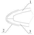
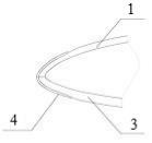
[0023] The leading edge structure of the airfoil is composed of the upper wall panel 1 of the wing surface, the lower wall panel 3 of the wing surface, and the middle 0.1mm thick aramid fiber cloth 4. There is a layer of 0.125mm thick carbon fiber cloth on the inner surface and outer surface of the upper wall panel 1 and the lower wing panel 3 respectively, and a 2mm thick PMI foam in the middle.

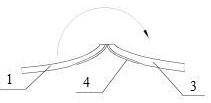
[0024] Manufacturing involves molds such as Figure 4 As shown, the surface of the airfoil and the lower wall plate are integrated together, the upper wall plate is turned 180° along the separation axis of the leading edge of the airfoil, and the leading edge of the upper wall plate is close to the leading edge of the lower wall plate along the separation axis , the mold is a solid structure, and the material is aluminum alloy. When using it, a layer of 0.1mm thick aramid cloth is symmetrically spread on the middle axis of the mold, and then a 0.125mm thick carbon fiber is laid on t...

Embodiment 2

[0026] The leading edge structure of the airfoil is composed of the upper wall plate 1 of the airfoil, the lower wall plate 3 of the airfoil and the middle 0.1mm thick nylon cloth 4. The inner surface and the outer surface of the plate 1 and the lower wall plate 3 of the airfoil each have a layer of 0.125mm thick carbon fiber cloth, and the middle is a 2mm thick PMI foam.

[0027] Manufacturing involves molds such as Figure 4 As shown, the surface of the wing surface and the lower wall plate are integrated together, the upper wall plate is turned 180° along the separation axis of the front edge of the wing, and the front edge of the upper wall plate is close to the front edge of the lower wall plate along the separation axis. The back of the mold is designed In order to reduce the groove structure, the material is steel. When using it, a layer of 0.1mm thick nylon cloth is laid symmetrically on the middle axis of the mold, and then a 0.125mm thick carbon fiber cloth is laid o...

Embodiment 3

[0029] The leading edge structure of the airfoil is composed of the upper wall panel 1 of the wing surface, the lower wall panel 3 of the wing surface, and the middle 0.1mm thick aramid fiber cloth 4. There is a layer of 0.125mm thick glass fiber cloth on the inner surface and outer surface of the upper wall panel 1 and the wing lower wall panel 3 respectively, with a 2mm thick PMI foam in the middle.

[0030] Manufacturing involves molds such as Figure 4 As shown, the surface of the airfoil and the lower wall plate are integrated together, the upper wall plate is turned 180° along the separation axis of the leading edge of the airfoil, and the leading edge of the upper wall plate is close to the leading edge of the lower wall plate along the separation axis , the mold is a solid structure, and the material is aluminum alloy. When using it, a layer of 0.1mm thick aramid cloth is symmetrically laid on the middle axis of the mold, and then a 0.125mm thick glass is laid on the o...


PUM

PropertyMeasurementUnit
thicknessaaaaaaaaaa
thicknessaaaaaaaaaa
thicknessaaaaaaaaaa

Abstract

The invention provides a micro-miniature unmanned aerial vehicle wing leading edge structure, a forming mold and a preparation method thereof, which belong to the technical field of unmanned aerial vehicles, can avoid cracking of the wing leading edge during use, and reduce production and processing costs while controlling the weight of the structure . In the present invention, the upper and lower wall panels are connected together through the flexible cloth layer at the leading edge. When the airfoil is not assembled into a complete airfoil, the upper and lower wall plates can be turned over along the axis of the flexible cloth layer at the leading edge, which is an integral joint structure. It can ensure that the leading edge of the airfoil does not crack without increasing the structural weight, labor intensity and cost; the corresponding forming mold is that the surface of the airfoil and the lower wall plate are in the same mold, and the upper wall plate is separated along the leading edge of the airfoil The axis is flipped by 180°, and the front edge of the upper wall plate is close to the front edge of the lower wall plate along the separation axis.

Description

technical field [0001] The invention relates to the technical field of unmanned aerial vehicles, in particular to a micro-miniature unmanned aerial vehicle wing leading edge structure, a molding die and a preparation method thereof. Background technique [0002] Due to its light weight and small load, micro-miniature UAVs have particularly strict requirements on the weight control of the body. Generally, the wing structure of UAV is composed of upper wall, lower wall, beams, ribs, etc. Among them, the upper and lower wall are mainly sandwich structure, the thickness is generally relatively thin, less than 3mm, and the front edge glued surface is small. . Such as figure 1 The traditional airfoil shown is divided into two separate panels, the upper panel 1 and the lower panel 3 of the wing. The method of locally increasing the thickness improves the effect of the glued surface, and then additionally spreads the cloth layer 2 to strengthen when the surface of the front edge ...

Claims


Application Information

Patent Timeline
Patent Type & Authority Patents(China)
IPC IPC(8): B64C3/14B64C3/26B64F5/10B29C70/34B29C33/00
CPCB64C3/14B64C3/26B64F5/10B29C33/00B29C70/342B64C2003/146B64U10/25Y02T50/40
Inventor 潘荣华黄志祥武震旭
Owner NANJING UNIV OF AERONAUTICS & ASTRONAUTICS
Why Eureka
Try Eureka