Al technical title is built by PatSnap Al team. It summarizes the technical point description of the patent document.
A methanol evaporator, compound technology, applied in the direction of evaporator accessories, evaporation, evaporator liquid feeder, etc., can solve the problems of low air utilization rate, increased production cost, low combination effect, etc., to save production time , improve utilization efficiency, uniform density effect
Pending Publication Date: 2022-03-01
葛聪聪
View PDF0 Cites 0 Cited by
Summary
Abstract
Description
Claims
Application Information
AI Technical Summary
This helps you quickly interpret patents by identifying the three key elements:
Problems solved by technology
Method used
Benefits of technology
Problems solved by technology
[0003] When the current methanol evaporator is in use, it is necessary to fully combine the air with the methanol liquid. In order to achieve the desired effect, the existing technical solution is to connect a gas pipeline at the bottom of the evaporator, and use pressurization to make the air Entering the interior of the evaporator through the gas pipeline, the air directly enters the methanol from the bottom to form bubbles, but the disadvantage of this technical solution is that only the surface of the bubbles can contact with methanol, the combination effect is not high, and the mixing method of liquid and gas is not effective. Obviously, the utilization rate of the blown air is not high, which increases the production cost
Method used
Image
Click on the blue label to locate the original text in one second.
Reading with bidirectional positioning of images and text.
Examples
Embodiment Construction
[0028] In order to make the technical means, creative features, goals and effects achieved by the present invention easy to understand, the present invention will be further described below in conjunction with specific embodiments.
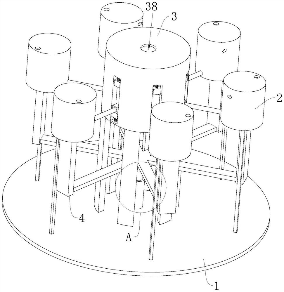
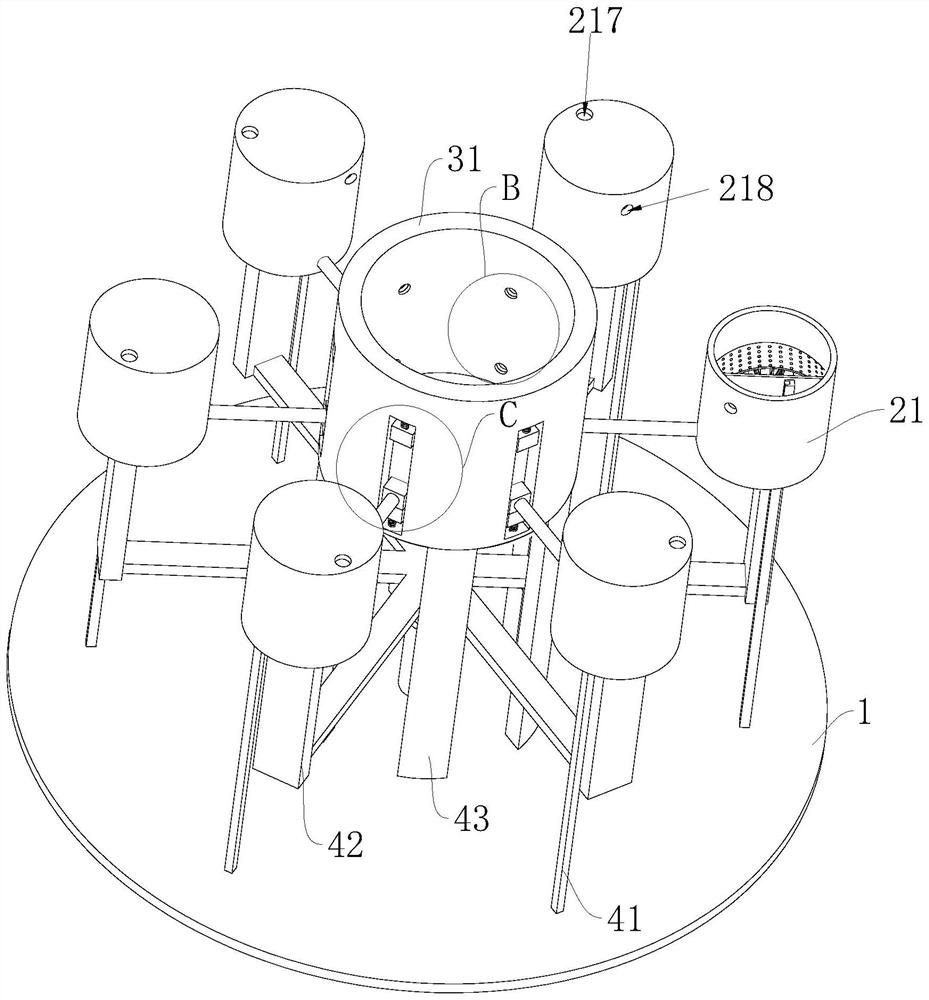
[0029] Such as Figure 1-Figure 10 As shown, a composite methanol evaporator according to the present invention includes a base 1 and a power mechanism 4, a power mechanism 4 is installed on one side of the base 1, a heating mechanism 2 is installed on one side of the power mechanism 4, and a heating mechanism 2 is installed on one side A supply mechanism 3 is installed;
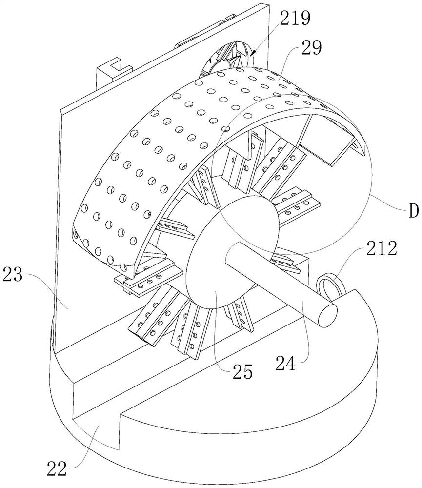
[0030] The heating mechanism 2 includes a heating shell 21, a liquid accumulation tank 22, a partition 23, a rotating shaft 24, a turntable 25, a blade plate 26, a groove 27, a heating plate 28, an arc plate 29, an impact plate 210, a volatilization hole 211, and a pipeline 212, the first sliding block 215 and the first sealing ring 216, the upper part of the base 1 is equipped...
PUM
Abstract
The invention relates to the technical field of methanol production, in particular to a composite methanol evaporator which comprises a base and a power mechanism, the power mechanism is mounted on one side of the base, a heating mechanism is mounted on one side of the power mechanism, and a supply mechanism is mounted on one side of the heating mechanism; the heating mechanism comprises a heating shell, a liquid accumulation groove, a partition plate, a rotating shaft, a rotating disc, a fan blade plate, a groove, a heating plate, an arc-shaped plate, an impact plate, a volatilization hole, a pipeline, a first sliding block and a first sealing ring, the heating shell is installed on the upper portion of the base, the liquid accumulation groove is formed in the bottom of the inner side of the heating shell, and the partition plate is fixedly installed at the bottom of the inner side of the heating shell. According to the invention, the heating mechanism is adopted, the groove takes away methanol through the liquid accumulation tank, the methanol in the liquid accumulation tank impacts the impact plate to form atomized methanol due to the action of centrifugal force, the atomized methanol is vaporized by the heat of the heating plate, the methanol liquid is vaporized after being vaporized, the methanol vaporization efficiency is improved, and the production time is saved.
Description
technical field [0001] The invention relates to the technical field of methanol production, in particular to a composite methanol evaporator. Background technique [0002] Methanol is the simplest saturated monohydric alcohol with a boiling point of 64.7°C. Because it was first discovered in retorted wood, it is also called "wood alcohol" or "wood essence". The methanol evaporator is one of the main equipment of the silver-methanol production plant, and its function is to generate the mixed gas of methanol and air. [0003] When the current methanol evaporator is in use, it is necessary to fully combine the air with the methanol liquid. In order to achieve the desired effect, the existing technical solution is to connect a gas pipeline at the bottom of the evaporator, and use pressurization to make the air Entering the interior of the evaporator through the gas pipeline, the air directly enters the methanol from the bottom to form bubbles, but the disadvantage of this tech...
Claims
Application Information
Patent Timeline
Application Date:The date an application was filed.
Publication Date:The date a patent or application was officially published.
First Publication Date:The earliest publication date of a patent with the same application number.
Issue Date:Publication date of the patent grant document.
PCT Entry Date:The Entry date of PCT National Phase.
Estimated Expiry Date:The statutory expiry date of a patent right according to the Patent Law, and it is the longest term of protection that the patent right can achieve without the termination of the patent right due to other reasons(Term extension factor has been taken into account ).
Invalid Date:Actual expiry date is based on effective date or publication date of legal transaction data of invalid patent.