Machine-made sand conditioning agent preparation device

A technology of sand conditioner and preparation device, applied in mechanical equipment, vibration suppression adjustment, mixer with rotary stirring device, etc., can solve the problems of poor use effect, low strength, poor preparation process, etc. The effect of avoiding damage to the device and improving the usability

Pending Publication Date: 2022-03-01
湖北升桦高分子建材有限公司
View PDF0 Cites 1 Cited by
  • Summary
  • Abstract
  • Description
  • Claims
  • Application Information

AI Technical Summary

Problems solved by technology

[0003] The traditional machine-made sand conditioner has a poor preparation process, and the structure of the preparation device is simple, resulting in poor use effect. The mac

Method used


Image

  • Machine-made sand conditioning agent preparation device
  • Machine-made sand conditioning agent preparation device
  • Machine-made sand conditioning agent preparation device

Examples


Embodiment 1

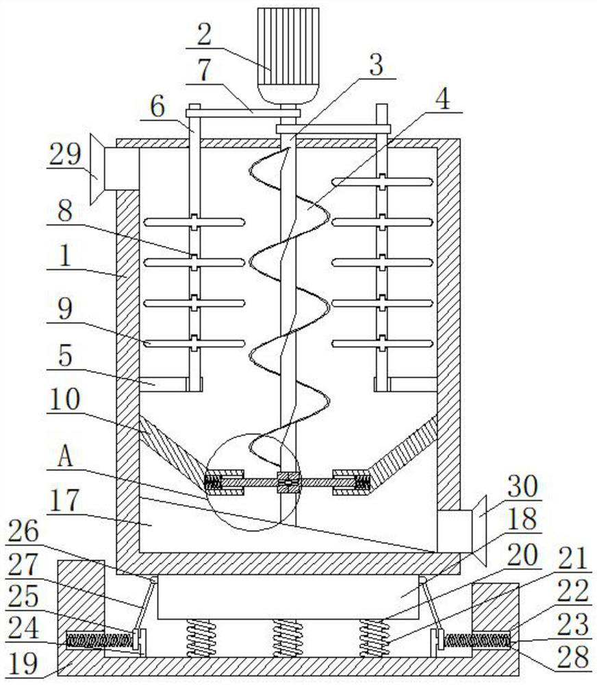
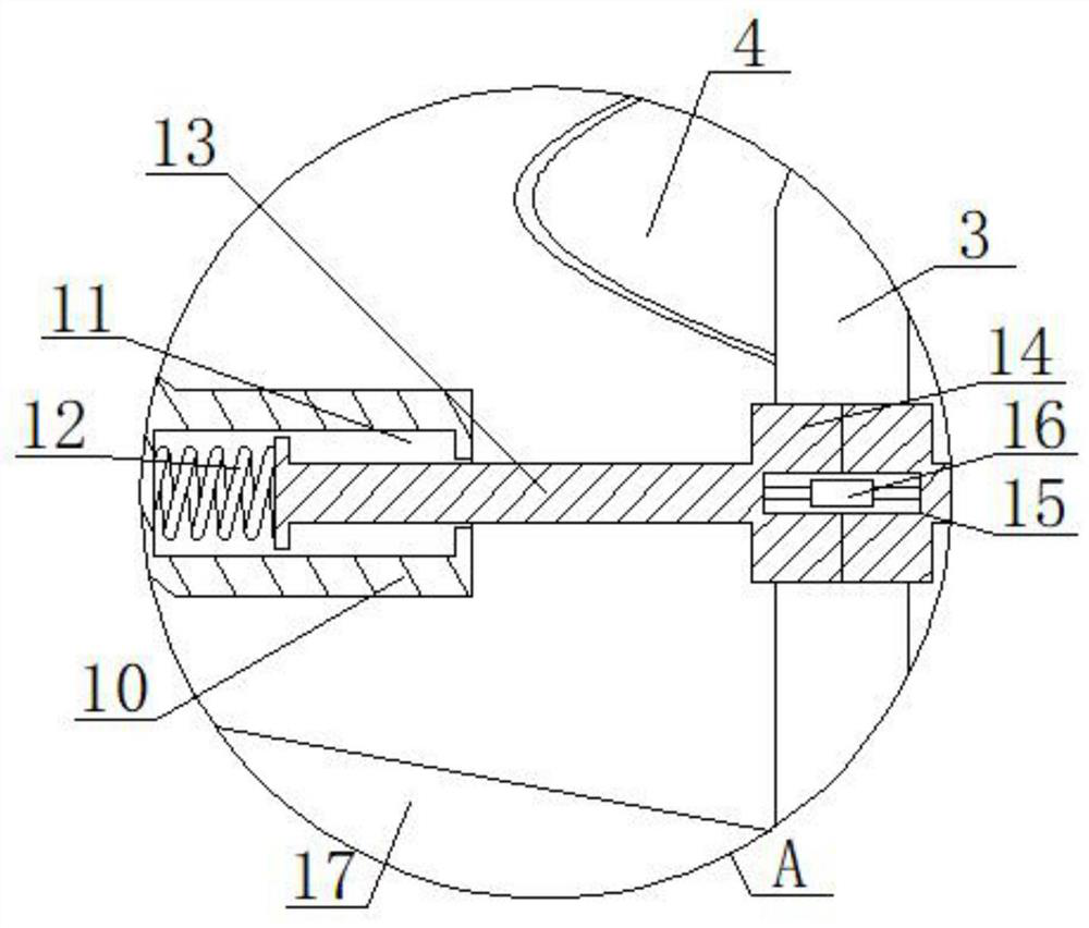
[0025] refer to Figure 1-2 , a machine-made sand conditioner preparation device, including a preparation box 1, the inside of the preparation box 1 is provided with a stirring mechanism and a buffer mechanism, the bottom of the preparation box 1 is provided with a shock absorbing mechanism, and the stirring mechanism is that the top of the preparation box 1 is fixedly connected with a motor 2, The power of the output shaft of the motor 2 is connected with a rotating shaft 3, and the other end of the rotating shaft 3 stretches into the preparation box 1. The tops of the rods 5 are all rotatably connected with a first rotating rod 6, and the other end of the first rotating rod 6 stretches out from the top of the preparation box 1, and the same belt 7 is slidably connected between the first rotating rod 6 and the rotating shaft 3, and the first rotating rod 6. A first chute 8 is evenly opened on the outer wall, and a first stirring rod 9 is slidably connected to the inner wall o...

Embodiment 2

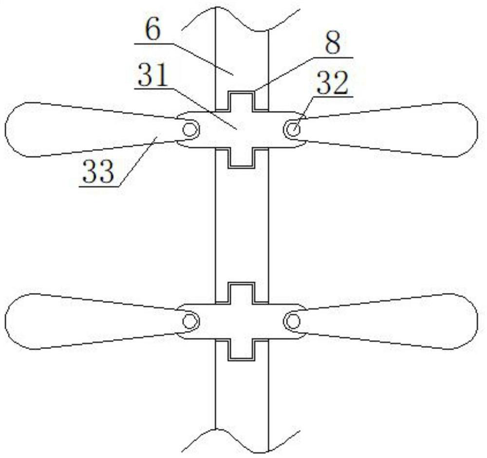
[0029] refer to image 3 , a machine-made sand conditioner preparation device. Compared with Embodiment 1, the inner wall of the first chute 8 is slidably connected with the second hoop 31, and the outer wall of the second hoop 31 is fixedly connected with the rotating bolt 32, and the rotating bolt 32 The outer wall is rotatably connected with a second stirring rod 33 .

[0030] Working principle: when in use, the second stirring rod 33 rotates around the rotating bolt 32 under the action of centrifugal force when the first rotating rod 6 rotates under the drive of the belt 7 through the second hoop 31 and the second stirring rod 33 , the machine-made sand conditioner raw material in the device is more fully stirred, which improves the stirring effect of the device and makes the preparation more complete.


PUM


Abstract

The invention discloses a machine-made sand regulator preparation device which comprises a preparation box, a stirring mechanism and a buffering mechanism are arranged in the preparation box, a damping mechanism is arranged at the bottom of the preparation box, the stirring mechanism is a motor fixedly connected to the top of the preparation box, a rotating shaft is in power connection with an output shaft of the motor, and the other end of the rotating shaft extends into the preparation box. The inner walls of the two sides of the preparation box are fixedly connected with supporting rods, the tops of the supporting rods are rotationally connected with first rotating rods, the other ends of the first rotating rods extend out of the top of the preparation box, and the inner walls of the first sliding grooves are slidably connected with first stirring rods. Through the arranged stirring mechanism, a motor is used for driving a rotating shaft to enable an auger blade to turn over materials in the preparation box upwards, meanwhile, a first rotating rod is driven by a belt to rotate, a first stirring rod is located in a first sliding groove to rotate, and the materials in the preparation box are stirred; and reduction of the preparation yield caused by caking of raw materials of the machine-made sand regulator is prevented.

Description

technical field [0001] The invention relates to the technical field of machine-made sand processing, in particular to a machine-made sand conditioner preparation device. Background technique [0002] As one of the most important building materials at present, machine-made sand concrete is used in almost all modern buildings. Among them, there are various forms of cement used in machine-made sand concrete, and slag cement is one of them. Since this kind of machine-made sand concrete makes full use of slag and steel slag, it can turn waste into treasure, so it has been widely promoted. [0003] The traditional machine-made sand conditioner has a poor preparation process, and the structure of the preparation device is simple, resulting in poor use effect. The machine-made sand concrete prepared by this machine-made sand conditioner has low strength, poor fluidity and encapsulation. Poor shortcomings, so can not meet the needs of users. Therefore, there is an urgent need for ...

Claims


Application Information

Patent Timeline
IPC IPC(8): B01F27/85B01F35/75F16F15/067
CPCF16F15/067
Inventor 肖国进曾泽军
Owner 湖北升桦高分子建材有限公司
Why Eureka
Try Eureka