Cooling equipment for processing control equipment

A technology for controlling equipment and equipment, which is applied in the direction of manufacturing tools, metal processing equipment, lighting and heating equipment, etc., can solve the problems of reducing the heat dissipation and cooling performance of devices, and achieve improved heat dissipation and cooling performance, good heat dissipation and cooling effects, and improved convenience Effect

Pending Publication Date: 2022-03-01
徐州宏武纳米科技有限公司
View PDF0 Cites 0 Cited by
  • Summary
  • Abstract
  • Description
  • Claims
  • Application Information

AI Technical Summary

Problems solved by technology

[0003] The prior art has the following deficiencies: the cooling equipment currently used for processing control equipment only uses a single method of spraying to cool down. This single cooling and heat dissipation structure can only be used on the top position of the control equipment processing heat dissipation, thereby reducing the cooling performance of the device

Method used


Image

  • Cooling equipment for processing control equipment
  • Cooling equipment for processing control equipment
  • Cooling equipment for processing control equipment

Examples


Embodiment Construction

[0020] The following will clearly and completely describe the technical solutions in the embodiments of the present invention with reference to the drawings in the embodiments of the present invention.

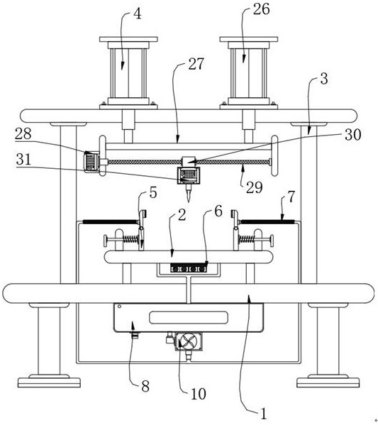
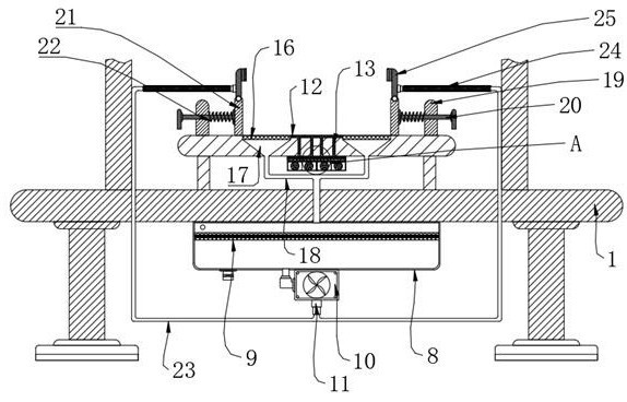
[0021] Such as Figure 1-4 As shown, the present invention provides a technical solution: a cooling device for control equipment processing, including a base 1, a working platform 2, a support frame 3, a processing component 4, a positioning component 5, a first heat dissipation component 6, a second heat dissipation component 7, A water tank 8 is installed in the middle of the bottom of the base 1 , a filter screen 9 is arranged on the inside of the top of the water tank 8 , a water pump 10 is installed at the bottom of the water tank 8 , and a working platform 2 is fixedly connected to the top of the base 1 . The platform 2 is provided with a first heat dissipation assembly 6, the two sides of the top of the working platform 2 are respectively provided with a positioning ass...


PUM


Abstract

The cooling equipment comprises a base, a working platform, a supporting frame, a machining assembly, a positioning assembly, a first heat dissipation assembly and a second heat dissipation assembly, a water tank is installed in the middle of the bottom of the base, a filter screen is arranged on the inner side of the top of the water tank, and a water pump is installed at the bottom of the water tank; a working platform is fixedly connected to the top of the base, a first heat dissipation assembly is arranged on the working platform, positioning assemblies are arranged on the two sides of the top of the working platform respectively, and second heat dissipation assemblies are arranged on the tops of the positioning assemblies. By arranging the water tank, the water pump, the first heat dissipation assembly and the second heat dissipation assembly, heat dissipation can be conducted on the top and the bottom of the machined control equipment at the same time, so that the heat dissipation and cooling performance of the device is improved, and meanwhile by arranging the working platform and the positioning assembly, a user can conveniently and rapidly fix the control equipment; and the use convenience of the device is improved.

Description

technical field [0001] The invention relates to the related technical field of control equipment processing, in particular to a cooling device for control equipment processing. Background technique [0002] Control equipment is a device used to control actuators and collect sensor data in the industrial production process. It includes the field control unit of the distributed control system, the programmable logic controller, and the remote terminal unit to control the production process. In the production process of control equipment, multiple processing steps are required, and in some processing processes, it is necessary to use cooling equipment to cool down the control equipment in the processing process. [0003] The prior art has the following deficiencies: the cooling equipment currently used for processing control equipment only uses a single method of spraying to cool down. This single cooling and heat dissipation structure can only be used on the top position of th...

Claims


Application Information

Patent Timeline
IPC IPC(8): B23Q11/12F25D1/02F25D17/02F25D17/06F28D21/00
CPCB23Q11/12F25D1/02F25D17/02F25D17/06F28D21/00Y02P70/10
Inventor 何卫林小小王建虎
Owner 徐州宏武纳米科技有限公司
Why Eureka
Try Eureka