Eureka AIR delivers breakthrough ideas for toughest innovation challenges, trusted by R&D personnel around the world.

Wing spar of a compound wing aircraft

An aircraft and composite wing technology, applied in the field of wing spars, can solve the problems of increasing the weight of the wing, too thick wing skin, and the stress concentration of the structure, so as to reduce the weight of the structure and improve the performance of bending and torsion resistance , light weight effect

Active Publication Date: 2022-04-12
中国空气动力研究与发展中心空天技术研究所
View PDF22 Cites 0 Cited by
  • Summary
  • Abstract
  • Description
  • Claims
  • Application Information

AI Technical Summary

Problems solved by technology

Among them, the mechanical properties of the beam-type wing are poor, the structure is prone to stress concentration, and the utilization rate of materials is not sufficient. For compound wing aircraft, the beam structure of the wing needs to have better bending and torsion performance , which is not available in the existing beam structure; relatively speaking, the monolithic structure improved on the basis of the beam structure overcomes the above shortcomings, and has better mechanical properties against bending and torsion. performance, but in order to obtain better bending and torsion performance, the wing skin is too thick, which increases the weight of the wing, which is not allowed by an aircraft with excellent performance

Method used


Image

  • Wing spar of a compound wing aircraft
  • Wing spar of a compound wing aircraft
  • Wing spar of a compound wing aircraft

Examples


Embodiment Construction

[0023] The specific embodiments of the present invention are described below to facilitate those skilled in the art to understand the present invention, but it should be clear that the present invention is not limited to the scope of the specific embodiments. For those of ordinary skill in the art, as long as various changes Such changes are obvious within the spirit and scope of the present invention as defined and determined by the appended claims, and all inventions and creations utilizing the inventive concept are within the scope of protection.

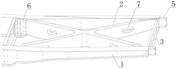
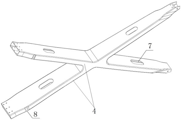
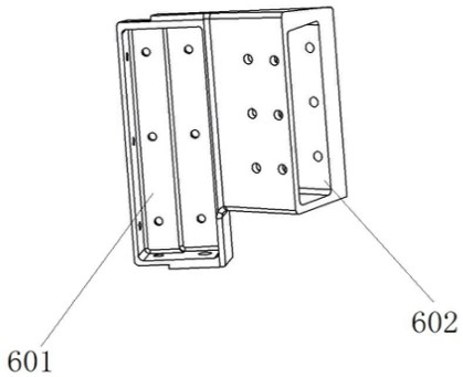
[0024] like Figure 1~Figure 5 As shown, the present invention provides a wing spar for a composite wing aircraft, which includes two horizontally aligned transverse integral beams 1, and a cross for carrying bending and torsional moments is arranged between the two transverse integral beams 1. The interior of the cross-type load-bearing beam 2 is a hollow structure, and the ends of the cross-type load-bearing beam 2 are fixedly ...


PUM


Abstract

The invention discloses a wing spar of a compound-wing aircraft, which comprises two transverse integral beams arranged horizontally opposite to each other, and a cross-type load-bearing beam for carrying bending and torsional moments is arranged between the two transverse integral beams. The interior of the cross-type load-bearing beam is a hollow structure, and the ends of the cross-type load-bearing beam are fixedly connected with two transverse integral beams; both ends of the two transverse integral beams are provided with an end rib for carrying bending and torsional moments. The two transverse integral beams are connected and fixed by two end ribs. The cross-type load-bearing beam has a hollow structure as a whole, which greatly reduces the structural weight of the wing. At the same time, the cross-type load-bearing beam greatly improves the resistance of the load-bearing beam Bending and torsional performance, the cross-type load-bearing beam is equipped with a water channel, which simply and effectively solves the problem of water storage and drainage inside the wing spar, and the addition of end ribs can obtain a lighter weight under the premise of determining a certain bending and torsional strength. the weight of.

Description

technical field [0001] The invention relates to the technical field of aircraft wing structures, in particular to a wing spar of a composite wing aircraft. Background technique [0002] At present, there are few researches on composite-wing UAVs at home and abroad, and the research on the fixed-wing spar form of composite-wing aircraft is even rarer. For the fixed-wing aircraft with the skin skeleton as the structural form: the wing spar is the main bearing structure of the aircraft, one of the important parts of the aircraft, and the premise to ensure the excellent performance of the aircraft. Wing spar, as the large main stress component of the aircraft wing, although it occupies a small proportion in the whole aircraft manufacturing, the wing spar of the aircraft, especially the wing spar of the large aircraft, has excellent performance due to its complex structure and stress condition. The technology of the spar appears crucial. [0003] The skin skeleton structure is ...

Claims


Application Information

Patent Timeline
Patent Type & Authority Patents(China)
IPC IPC(8): B64C3/18
CPCB64C3/185
Inventor 吴文华鞠金龙苏运来涂梦蕾周胜任吴振元白兴之高福奎逯明清李迎翔邢贝贝李鹏
Owner 中国空气动力研究与发展中心空天技术研究所
Why Eureka
Eureka Blog
Learn More