Segmented convergent type plugging machine for piping emergency rescue
A technology of piping and rods, which is applied in the field of segmented piping emergency plugging machines, can solve problems such as difficult to tightly block piping channels, and achieve the effect of reducing water flow disturbance and reducing the possibility
- Summary
- Abstract
- Description
- Claims
- Application Information
AI Technical Summary
Problems solved by technology
Method used
Image
Examples
Embodiment 1
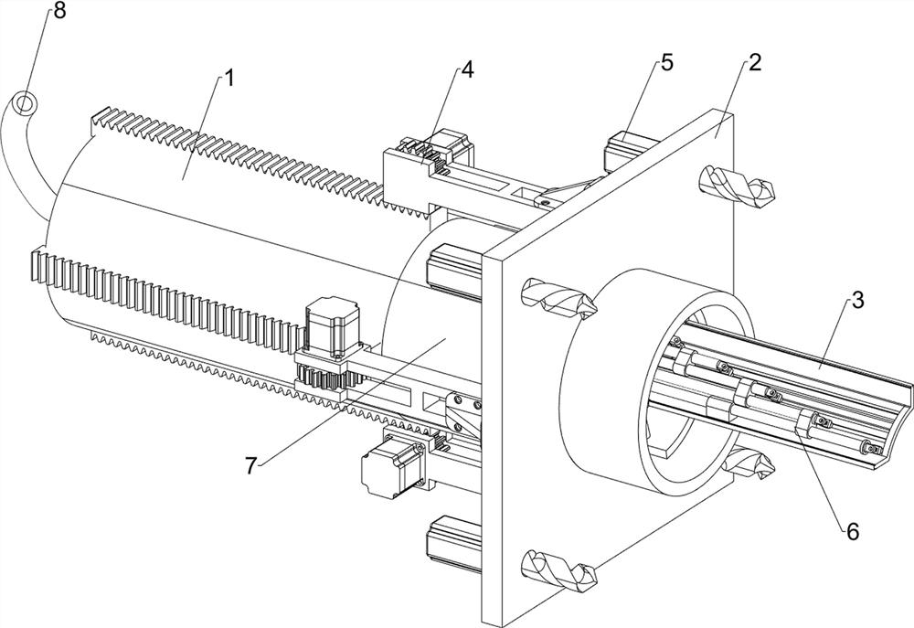
[0038] A segmented and bundled piping emergency plugging machine, such as Figure 1-11 As shown, it includes a first installation frame 1, a bundle assembly 6 and a feed pipe 8; a bundle assembly 6 is installed on the right of the first installation frame 1; a feed pipe 8 is arranged in the first installation frame 1 .
[0039] The first mounting rack 1 includes a second mounting rack 101 , a third mounting rack 102 and a connecting plate 103 ; a connecting plate 103 is welded on the right part of the inner wall of the second mounting rack 101 ; the inner front side of the second mounting rack 101 Connect the bundle assembly 6; the right part of the outer surface of the connecting plate 103 is welded with a third installation frame 102, and the third installation frame 102 is located to the right of the second installation frame 101; bundle assembly 6.
[0040] The collection assembly 6 includes a first base 601, a third waterproof motor 602, a second gear 603, a first singl...
Embodiment 2
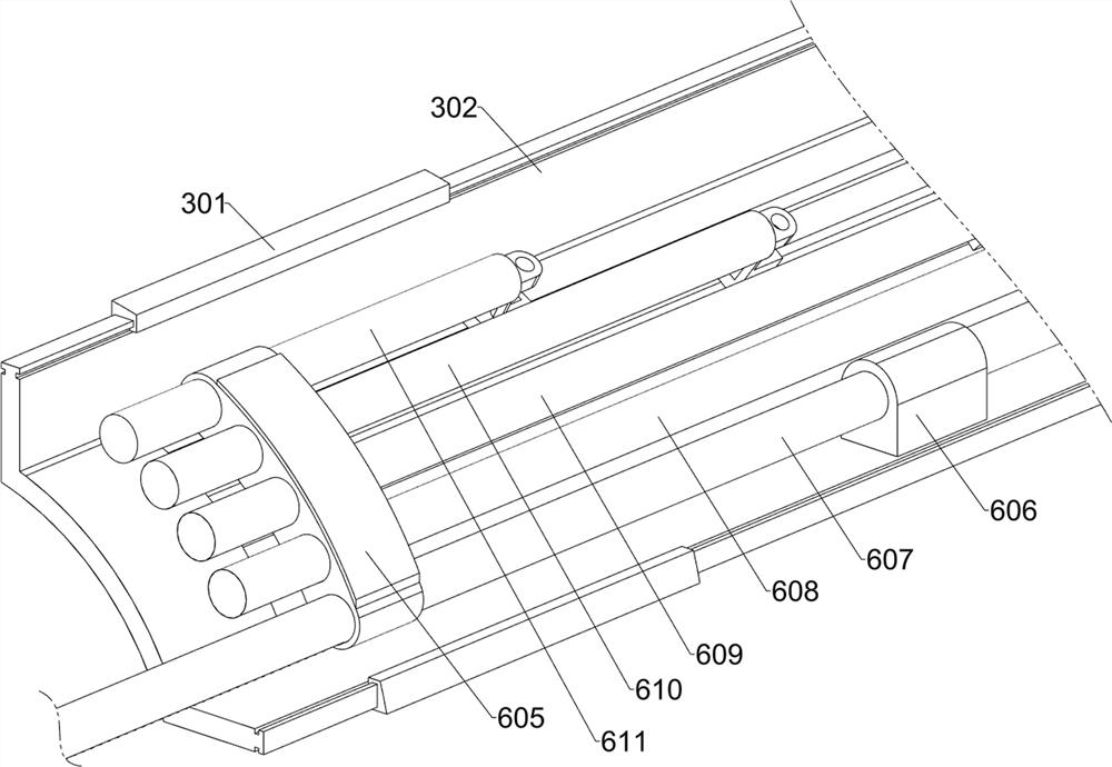
[0045] On the basis of Example 1, as figure 1 , Figure 5-6 and Figure 12 As shown, it also includes a positioning plate 2, a moving baffle 3, a propulsion assembly 4 and a positioning assembly 5; the right part of the first installation frame 1 is connected with a positioning plate 2; The moving baffle 3; the moving baffle 3 is connected with the second single-hole limit frame 606; the outer surface of the first installation frame 1 is connected with the propulsion assembly 4; the left side of the positioning plate 2 is connected with the propulsion assembly 4; the positioning plate 2 is connected There are positioning components 5.
[0046] The movable baffle 3 includes a limit guide rail 301 and a protective plate 302; two limit guide rails 301 are fixedly connected to the upper part of the inner front of the third installation frame 102; a protective plate 302 is installed on the two limit guide rails 301; A second single-hole limiting frame 606 is welded in the middle...
Embodiment 3
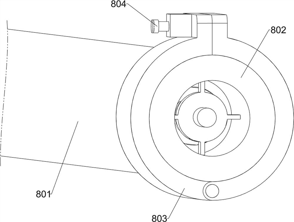
[0052] On the basis of Example 2, as figure 1 and Figure 14-15 As shown, a tamping assembly 7 is also included; the inner side of the connecting plate 103 is connected with the tamping assembly 7 ; the inner side of the tamping assembly 7 is connected with the feeding hose 801 .
[0053] The compaction assembly 7 includes a fourth mounting frame 701, a limit ring 702, a first elastic member 703, a striker 704, a second base 705, a fourth waterproof motor 706, a helical gear 707, a toothed disc 708, a wheel disc 709 and The connecting ring 710; the fourth mounting frame 701 is welded on the connecting plate 103; the inner side of the fourth mounting frame 701 is fixedly connected with the feeding hose 801; A limit ring 702; each limit ring 702 is provided with four hollow sliding grooves equidistantly around the outer ring surface, and each groove is provided with a first elastic member 703; one end of each first elastic member 703 is Connected to the adjacent limit rings 70...
PUM
 Abstract
Description
Claims
Application Information
 - R&D
- Intellectual Property
- Life Sciences
- Materials
- Tech Scout
- Unparalleled Data Quality
- Higher Quality Content
- 60% Fewer Hallucinations
Browse by: Latest US Patents, China's latest patents, Technical Efficacy Thesaurus, Application Domain, Technology Topic, Popular Technical Reports.
© 2025 PatSnap. All rights reserved.Legal|Privacy policy|Modern Slavery Act Transparency Statement|Sitemap|About US| Contact US: help@patsnap.com


