Airtight rectangular window for ship
A rectangular window and airtight technology, which is applied in the direction of windows/doors, sealing devices, door/window accessories, etc., can solve the problems of not being suitable for large cruise ships to watch and use, the size limitation of window opening, and the limitation of user experience, so as to achieve good ventilation The effect of environment and observation field of view, ensuring safety and ensuring stability
- Summary
- Abstract
- Description
- Claims
- Application Information
AI Technical Summary
Problems solved by technology
Method used
Image
Examples
Embodiment 1
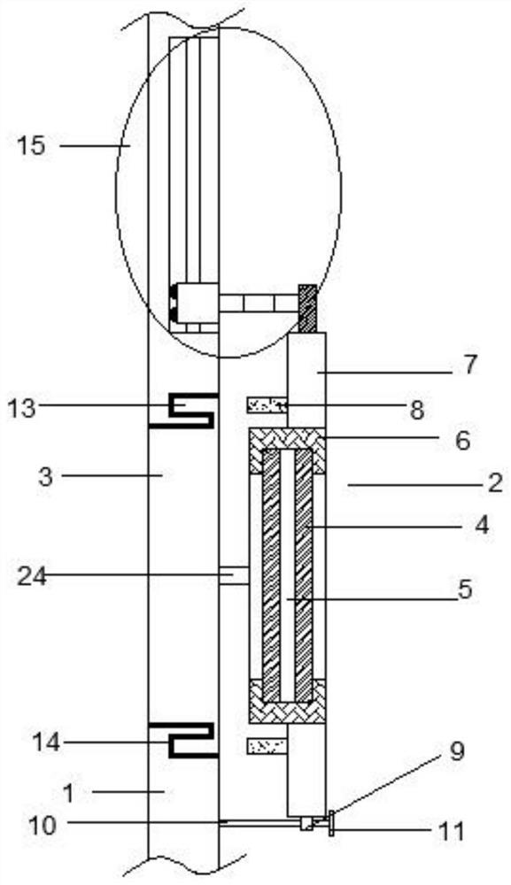
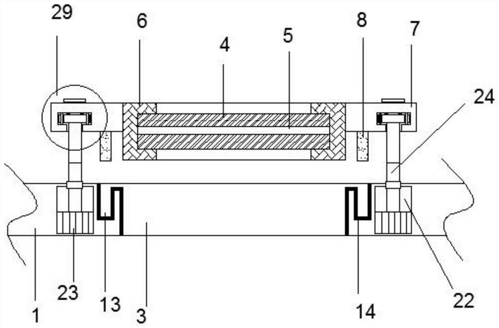
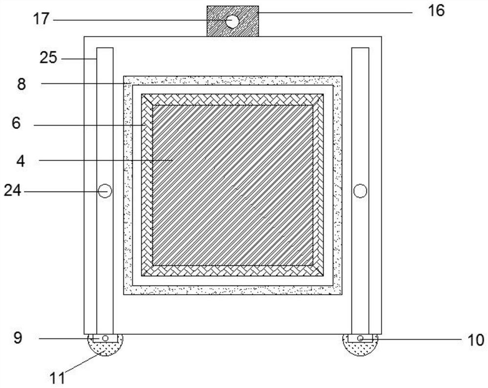
[0031] refer to Figure 1-6 , an airtight rectangular window for ships, comprising a wall 1, a through hole 3 provided on the wall 1 and a window 2 matching the through hole 3, the window 2 includes a glass plate 4 and a glass plate arranged in the center 4 The window cover 6 wrapped around, the outside of the window cover 6 is provided with a ring of outer guard plate 7, the window cover 6 is protruding to the left compared with the outer guard plate 7, and the inner wall of the through hole 3 is provided with a Layer sealing layer 14, the protruding part of the window cover 6 is connected with the sealing layer 14 on the through hole 3, and the front and rear sides of the left end of the outer guard plate 7 are symmetrically provided with a push-pull mechanism, and the push-pull mechanism includes the right end of the wall body 1 The installation groove 22 provided inside and the sliding mechanism 29 provided on the outer guard plate 7, the inside of the installation groove ...
Embodiment 2
[0035] refer to Figure 1-6 , this embodiment is basically the same as Embodiment 1. Preferably, the sliding mechanism includes a T-shaped moving groove 25 provided at the left end of the outer guard plate 7 and a sliding plate 9 slidingly connected inside the moving groove 25, and the lower end of the moving groove 25 is The opening communicates with the outside, and the right end of the second telescopic rod 24 is fixed to the center of the left end of the sliding plate 9 , and the sliding plate 9 is slidably connected to the inner wall of the moving groove 25 . It can effectively guarantee the stability of the form 2 lifting suspension.
[0036] In order to further improve the smoothness of movement of the window 1 , preferably, the right end of the sliding plate 9 and the moving groove 25 are slidably connected by a plurality of second balls 28 .
[0037] In order to facilitate the guidance of the window 2 and the stability during opening and closing, preferably, the bott...
Embodiment 3
[0040] refer to Figure 1-6 , this embodiment is basically the same as Embodiment 2. Preferably, the glass plate 4 inside the window cover 6 has a double-layer structure, and a hollow layer 5 is arranged between the double-layer glass plates 4 . Effectively ensure airtightness while improving sound insulation and temperature insulation effects,
[0041] In order to facilitate the opening and closing of the window and ensure the positioning accuracy of the opening and closing, preferably, a circle of flashboard 8 is arranged at the left end of the outer guard plate 7, and the flashboard 8 is arranged between the sliding mechanism 29 and the window cover 6, so that The right side of the wall body 1 is provided with a circle of slots 13 matching the plugboard 8, and the plugboard 8 is connected to the slot 13.
[0042] In order to further improve the airtightness of the window, preferably, the sealing layer 14 on the side wall of the through hole 3 is extended and laid on the in...
PUM
 Abstract
Description
Claims
Application Information
 - R&D
- Intellectual Property
- Life Sciences
- Materials
- Tech Scout
- Unparalleled Data Quality
- Higher Quality Content
- 60% Fewer Hallucinations
Browse by: Latest US Patents, China's latest patents, Technical Efficacy Thesaurus, Application Domain, Technology Topic, Popular Technical Reports.
© 2025 PatSnap. All rights reserved.Legal|Privacy policy|Modern Slavery Act Transparency Statement|Sitemap|About US| Contact US: help@patsnap.com


