Cooling device and cooling method for engine room generator set
A generator set and cooling method technology, applied in the direction of machine/engine, engine cooling, mechanical equipment, etc., can solve the problem of poor cooling effect of engine room generator set
- Summary
- Abstract
- Description
- Claims
- Application Information
AI Technical Summary
Problems solved by technology
Method used
Image

Examples
Embodiment 1
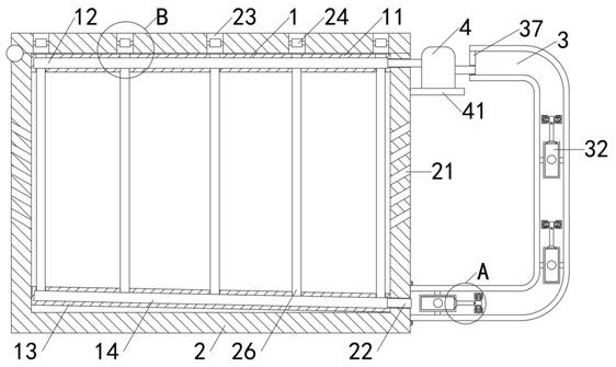
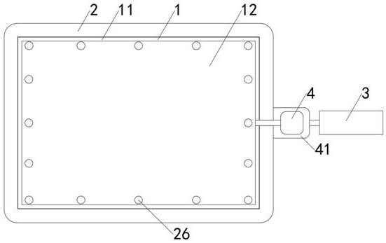
[0033] Embodiment 1, with reference to attached Figure 1-Figure 5 , a cooling device and cooling method for a generator set in a nacelle provided by the present invention, comprising a supporting circulation device 1, a nacelle 2, a square hollow tube 3 and a condenser 4;
[0034]Further, the support circulation device 1 includes a cooling square plate 11, the inner wall of the top of the cabin 2 is inserted into the cooling square plate 11, and the inner wall of the cooling square plate 11 is provided with a water inlet tank 12, and the engine room 2 The inner wall of the bottom end is inserted into the cooling square plate 2 13, the inner wall of the cooling square plate 13 is provided with a water outlet 14, the inner wall of the top of the cooling square plate 11 is arranged in a square shape and evenly provided with air inlet holes 25, and the engine room The angle between 2 and the cooling square plate 2 13 is 10°-30°. Specifically, the water inlet tank 12 has the effec...
Embodiment 2
[0043] Embodiment 2, with reference to attached Figure 6-Figure 7 , a cooling device and cooling method for a generator set in a nacelle provided by the present invention, including a supporting circulation device 1 , a nacelle 2 , a square hollow tube 3 and a condenser 4 .
[0044] Further, the support circulation device 1 also includes a hollow cooling plate 15, the inner wall of the top of the cabin 2 is plugged with the hollow cooling plate 15, and the inner wall of the hollow cooling plate 15 is provided with a water inlet tank 2 16, the Hollow cooling plate 2 17 is plugged into the inner wall of the bottom end of the nacelle 2, and the inner wall of the hollow cooling plate 17 is provided with a water outlet 2 18, and the inner wall of the top of the hollow cooling plate 15 is arranged in a square shape and evenly provided with the air inlet holes 25, The included angle between the nacelle 2 and the hollow cooling plate 2 17 is 10°-30°. Specifically, the water inlet tan...
Embodiment 3
[0049] A method for cooling a generator set in a nacelle, further comprising specific steps as follows:
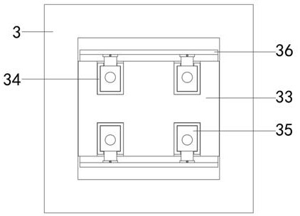
[0050] S1, when the generator set is working, the bottom hydraulic cylinder 2 35 will drive the U-shaped extruding plate 36 to elongate, and the elongated bottom U-shaped extruding plate 36 will be attached to the inner wall of the square hollow tube 3, thereby achieving sealing effect, then the bottom hydraulic cylinder 32 will drive the bottom push plate 33 to elongate, and the elongated bottom push plate 33 will push the coolant through the elongated bottom U-shaped extrusion plate 36, and then the coolant will be in the Move up in the square hollow tube 3.
[0051] S2, when the coolant moves to the middle hydraulic cylinder one 32 position, the U-shaped extrusion plate 36 in the middle will be stretched through the middle hydraulic cylinder two 35 until it fits in the inner wall of the square hollow tube 3, and then the middle hydraulic cylinder One 32 will drive the ...
PUM
 Abstract
Description
Claims
Application Information
 - R&D
- Intellectual Property
- Life Sciences
- Materials
- Tech Scout
- Unparalleled Data Quality
- Higher Quality Content
- 60% Fewer Hallucinations
Browse by: Latest US Patents, China's latest patents, Technical Efficacy Thesaurus, Application Domain, Technology Topic, Popular Technical Reports.
© 2025 PatSnap. All rights reserved.Legal|Privacy policy|Modern Slavery Act Transparency Statement|Sitemap|About US| Contact US: help@patsnap.com