Continuous monitoring device and method for deformation of permanent steel formwork in construction period

A technology for monitoring devices and steel templates, applied in measuring devices, using optical devices, measuring heat, etc., can solve problems such as weak construction quality control, achieve the effects of guiding subsequent construction and maintenance, reducing economic losses, and improving sensitivity

Pending Publication Date: 2022-03-01
浙江省水利水电勘测设计院有限责任公司
View PDF8 Cites 0 Cited by
  • Summary
  • Abstract
  • Description
  • Claims
  • Application Information

AI Technical Summary

Problems solved by technology

[0004] In order to overcome the deficiencies of the existing two steel formwork deformation monitoring methods, realize continuous deformation monitoring of steel formwork in time and space, and solve the problem of weak construction quality control, the present invention proposes a permanent steel formwork deformation continuous monitoring device during construction and method, not only can realize automatic continuous monitoring, but also not restricted by the environmental factors of the construction site

Method used


Image

  • Continuous monitoring device and method for deformation of permanent steel formwork in construction period
  • Continuous monitoring device and method for deformation of permanent steel formwork in construction period
  • Continuous monitoring device and method for deformation of permanent steel formwork in construction period

Examples


Embodiment Construction

[0036] Below in conjunction with accompanying drawing, the present invention is described in further detail:

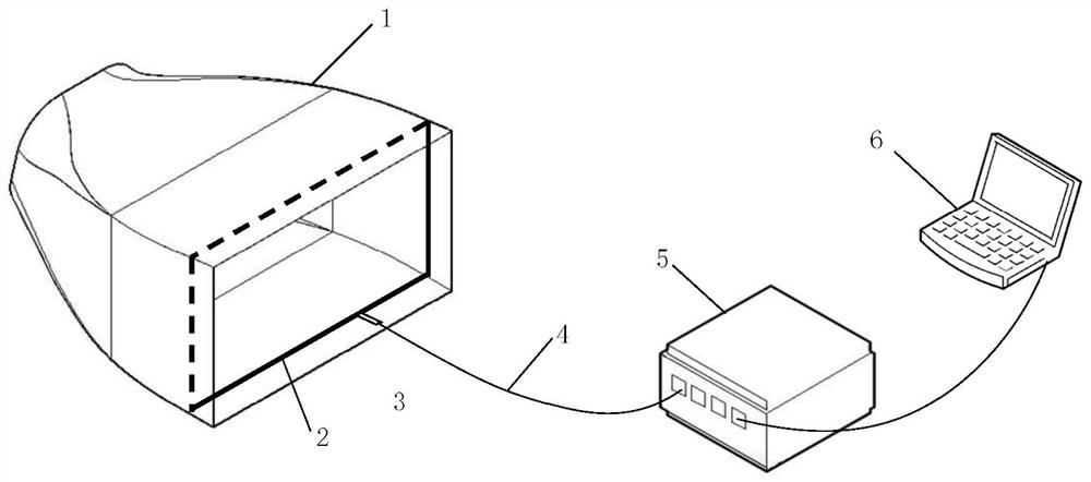
[0037] Such as figure 1 As shown, the present invention proposes a continuous monitoring device for permanent steel formwork deformation during construction, including: sensing optical fiber 2, protective fixture 3, communication optical fiber 4, optical nanometer 5, data processing terminal 6, and optical fiber fusion splicer, laser optical fiber Experimental tools such as test pens.

[0038] Sensing optical fiber 2 includes temperature sensing optical fiber and strain sensing optical fiber. Sensing optical fiber 2 is completely fixed to the monitoring surface of permanent steel template 1. Sensing optical fiber 2 is connected to photonometer 5 through communication optical fiber 4.

[0039] The protective clamp 3 is located at the outgoing position of the sensing optical fiber 2, and is used to protect the core of the sensing optical fiber 2 leading out.

[0040] ...


PUM


Abstract

The invention discloses a continuous monitoring device and method for deformation of a permanent steel formwork in a construction period. The device comprises a sensing optical fiber, a protection clamp, a communication optical fiber, a photometer, a data processing terminal, an optical fiber fusion splicer and a laser optical fiber test pen. The sensing optical fiber is completely fixed with the monitoring surface of the permanent steel template, and the sensing optical fiber is connected with the spectrometer through the communication optical fiber; the protection clamp is located at a sensing optical fiber outgoing position and used for protecting a fiber core led out of the sensing optical fiber; the communication optical fiber is used as a channel for releasing detection light and receiving scattered light by the light receiving instrument; and the spectrometer is also connected with the data processing terminal. The method comprises the steps of indoor experiment, field arrangement, continuous monitoring, data processing and the like. The method is not interfered by environmental factors, deformation and temperature change of the steel formwork can be monitored in real time in the runner concrete pouring period, forecasting and early warning are achieved, follow-up construction and maintenance are effectively guided, economic losses are reduced, and the method has great application value.

Description

technical field [0001] The invention relates to the deformation measurement technology of steel structures, in particular to the deformation monitoring technology of permanent steel formwork in water conservancy projects, specifically a device and method for continuous monitoring of deformation of permanent steel formwork during construction, which uses distributed optical fibers to carry out deformation of permanent steel formwork in water conservancy projects Monitoring, taking into account the heat of hydration generated by concrete pouring and the measurement of ambient temperature. Background technique [0002] The permanent steel formwork in water conservancy projects is generally a complex special-shaped surface structure, which is mainly used for complex concrete construction such as draft tubes, volutes, gate piers, and water passages. The gradual cross-section size of the flow channel structure is generally determined by fluid mechanics calculations and finalized a...

Claims


Application Information

Patent Timeline
Patent Type & Authority Applications(China)
IPC IPC(8): G01B11/16G01K11/322
CPCG01B11/16G01K11/322
Inventor 虞鸿包腾飞霍恒炎裘华锋王一兵
Owner 浙江省水利水电勘测设计院有限责任公司
Why Eureka
Try Eureka