Object mass center measuring device and object mass center measuring method

A measuring device and object technology, applied in the field of object centroid measuring devices, can solve problems such as low measurement accuracy, and achieve the effects of improving measurement accuracy, improving measurement efficiency, and simplifying structure

Pending Publication Date: 2022-03-01
ZHENGZHOU RES INST OF MECHANICAL ENG CO LTD
View PDF1 Cites 2 Cited by
  • Summary
  • Abstract
  • Description
  • Claims
  • Application Information

AI Technical Summary

Problems solved by technology

[0005] The object of the present invention is to provide a device for measuring the center of mass of an object to solve the technical problem of low measurement accuracy of the three-point or four-point support weighing method in the prior art. The present invention also provides a method for measuring the center of mass of an object to Solve the technical problem of low measurement accuracy of the three-point or four-point support weighing method in the prior art

Method used


Image

  • Object mass center measuring device and object mass center measuring method
  • Object mass center measuring device and object mass center measuring method
  • Object mass center measuring device and object mass center measuring method

Examples


Embodiment 1

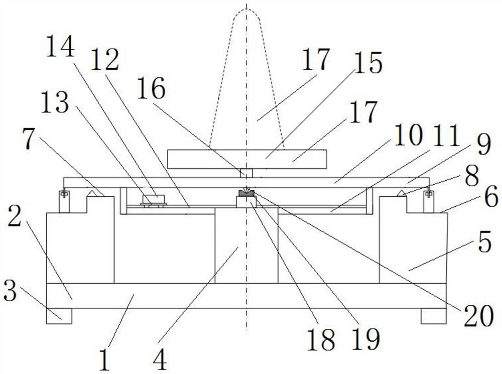
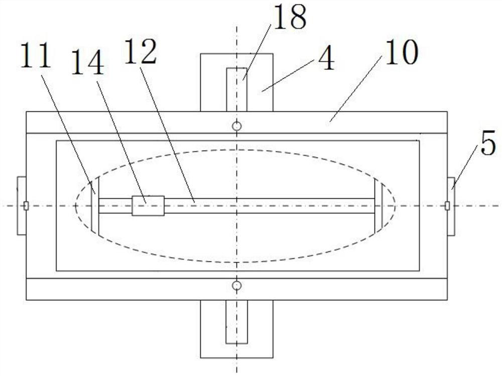
[0044] Such as figure 1 and figure 2 As shown, the object centroid measuring device includes a device base 1, on which an object bearing seat 9 and a balance detection device are arranged, the object bearing seat 9 is used for placing the object 17 to be measured, and the balance detection device is used to detect the position of the object bearing seat 9 Balanced state.

[0045] The device base 1 includes a rectangular bottom plate 2 , four support legs 3 are provided under the bottom plate 2 , and the four support legs 3 are respectively provided at the four corners of the bottom plate 2 to support the entire device base 1 . The length direction of the base plate 2 is the left-right direction, and the width direction of the base plate 2 is the front-rear direction.

[0046] The object bearing seat 9 is a frame-mounted structure as a whole, including a seat body 10 and a weight bracket 11 .

[0047] The seat body 10 is a rectangular plate-shaped structure, and a turntable...

Embodiment 2

[0059] The difference between this embodiment and Embodiment 1 is that in Embodiment 1, a turntable 15 is provided on the object bearing seat 9, and the object to be measured 17 is placed on the turntable 15, and the difference of the object to be measured 17 can be measured by rotating the turntable 15. The centroid in the direction. And in the present embodiment, turntable is no longer set on the object bearing seat 9, and the object to be measured 17 is placed on the weight bracket 11 of sinking of the object bearing seat 9, in the present embodiment, to measure the parallel storage tank of aircraft 30 centroid as an example to introduce, such as Figure 4 Shown:

[0060] The seat body 10 of the object bearing seat 9 is provided with a through hole adapted to the shape of the parallel storage tank 30 for the parallel storage tank 30 to pass through the object bearing base 9 and be placed on the weight bracket 11 .

[0061] The weight bracket 11 is provided with an upper s...

Embodiment 3

[0069] The difference between this embodiment and Embodiment 1 is that in Embodiment 1, a linear motor module 13 is provided on the weight guide seat 12, a mover tray 14 is arranged on the linear motor module 13, and the weight is placed on the mover On the tray 14, the linear motor module 13 drives the mover tray 14 to move with the weight. In this embodiment, the mover tray 14 is directly guided to the assembly weight guide seat 12, a laser displacement sensor is set on the swing support table 4, and the mover tray 14 is manually moved, the value measured by the laser displacement sensor is the weight to The distance of the swing axis of the object bearing seat 9.


PUM


Abstract

The invention relates to an object centroid measuring device and an object centroid measuring method, the object centroid measuring device comprises a device base, an object bearing seat for bearing an object to be measured is arranged on the device base, and a swing supporting structure is arranged between the object bearing seat and the device base for the object bearing seat to swing along a swing axis extending horizontally. A balance detection device used for detecting the balance state of the object bearing seat is further arranged between the object bearing seat and the device base. The object bearing seat is provided with a weight guide seat which extends along a straight line and is used for guiding the weight to move, the straight line where the extension direction of the weight guide seat is located is perpendicular to the swing axis of the object bearing seat, and the object mass center measuring device further comprises a distance obtaining structure used for obtaining the distance between the weight and the swing axis; a weighing sensor is arranged on the device base, and the swing supporting structure is arranged between the weighing sensor and the object bearing seat and used for measuring the total mass of the object bearing seat and an object to be measured placed on the object bearing seat.

Description

technical field [0001] The invention belongs to the field of mechanical balance detection, and in particular relates to a device for measuring the center of mass of an object and a method for measuring the center of mass of an object. Background technique [0002] The center of mass plays an important role in some occasions, for example, it is an important quality characteristic parameter of the aircraft. Therefore, in the process of production and assembly, it is necessary to accurately measure the center of mass of the object. There are also dynamic centroid measurement requirements in actual engineering, such as for storing liquid tanks, when liquid needs to be discharged or injected during use, there will be dynamic changes in the centroid. And for the storage tanks with parallel structure, the liquid is discharged or injected through the parallel pipelines, and the amount of liquid injected or discharged by different pipelines is different, so there will also be dynamic...

Claims


Application Information

Patent Timeline
Patent Type & Authority Applications(China)
IPC IPC(8): G01M1/12G01G21/22G01G21/23G01G21/24
CPCG01M1/125G01G21/22G01G21/235G01G21/241
Inventor 武艺泳卢志辉孙志杨张磊乐杨洪涛郑国良刘珉
Owner ZHENGZHOU RES INST OF MECHANICAL ENG CO LTD
Why Eureka
Try Eureka